
Microchannel array and method for producing the same, and blood measuring method employing it

a microchannel array and microchannel array technology, applied in the field of microchannel array, a manufacturing method and a blood test method, can solve the problems of increased medical care costs, increased number of people in between healthy and diseased, and low efficiency

Inactive Publication Date: 2009-06-11
KURARAY CO LTD
View PDF4 Cites 25 Cited by
  • Summary
  • Abstract
  • Description
  • Claims
  • Application Information

AI Technical Summary

Benefits of technology

[0012]The present invention has been accomplished to solve the above problems and an object of the present invention is thus to provide a microchannel array with more complex flow channels formed by a simple method, a method of manufacturing the same, and a blood test method using the same.

Problems solved by technology

It is expected that more and more individuals will place a higher value on preventive medicine than on curative medicine because of an increase in medical care costs, a fact that disease prevention is less costly than treatment, and an increase in the number of those who are in between healthy and diseased.
However, the above measurement methods have problems such as low efficiency, low reproducibility and low quantitative ability, and therefore they fail to serve as effective measurement methods that are adequate for the importance of measurement.
Further, the conventional platelet aggregability measurement method requires time and labor for sample preparation and its sensitivity is not sufficient.
Furthermore, the conventional red blood cell deformability measurement method is lack of reliability because openings or grooves can be obstructed by the formed components in a blood sample during measurement.
This degrades the physiological or diagnostic values of the measurement results.

Method used


Image

  • Microchannel array and method for producing the same, and blood measuring method employing it
  • Microchannel array and method for producing the same, and blood measuring method employing it
  • Microchannel array and method for producing the same, and blood measuring method employing it

Examples


example 1

[0230]A blood test with the use of the above-described microchannel array A is described with the case of performing blood fluidity measurement. A blood sample is the same specimen as that used in the comparative microchannel array X.

[0231]Although the blood platelets started to adhere onto the wall surface before reaching the microgroove after 20 seconds from the passage of blood and the micro flow channel was occluded by the aggregates in the comparative microchannel array X, the adhesion of blood platelets did not occur under the same conditions in the microchannel array A. When using the microchannel array A, blood platelets adhered onto the wall surface after passing through the micro flow channel after 30 seconds from the passage of blood. It was observed that red blood cells and white blood cells, which are other blood cell components, were deformed and passed through the channel, thus exhibiting the morphology of normal blood components.

[0232]A passage time of blood was shor...

example 2

[0234]A blood test with the use of the above-described microchannel array B is described with the case of performing blood fluidity measurement. A blood sample is the same specimen as that used in the comparative microchannel array X.

[0235]Like the example 1, the adhesion of blood platelets onto the surface before reaching the micro flow channel did not occur, and the blood platelets adhered onto the surface after passing through the micro flow channel after 30 seconds. It was observed that red blood cells and white blood cells, which are other blood cell components, were deformed and passed through the channel, thus exhibiting the morphology of normal blood components.

[0236]A passage time of blood was 50 seconds, which is shorter than that in the example 1. Although the first substrate 10 of the microchannel array A that was used in the example 1 had the flow channel of one-level structure with a depth of 300 μm, the first substrate 10b of the example 2 had the flow channel of two-...

example 3

[0238]A blood test with the use of the above-described microchannel array C is described with the case of performing blood fluidity measurement. A blood sample was the same specimen as that used in the comparative microchannel array X.

[0239]The microchannel array C includes the flow channels that are formed by the microgrooves 27c and have three types of dimensions (a) a flow channel length of 30 μm and a depth of 5 μm, (b) a flow channel length of 15 μm and a depth of 5 μm, and (c) a flow channel length of 5 μm and a depth of 5 μm for the purpose of obtaining detailed information of the sensitivity of blood platelets of the blood of a test subject to the shear stress as described above.

[0240]The surface modification for anti-blood adhesion was performed by coating an organic material (the product name: Lipidure-PMB, a copolymer of MPC polymer having phospholipid polar group and butyl acrylate). Like the example 1, the adhesion of blood platelets onto the surface before reaching the...


PUM


Abstract

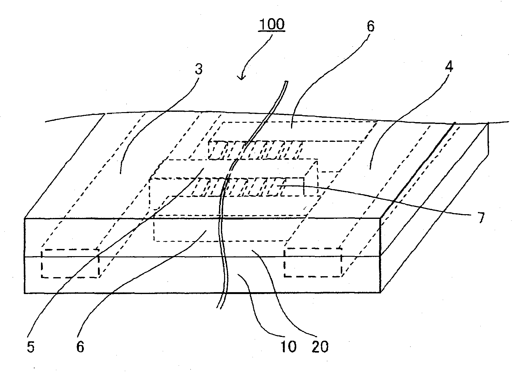
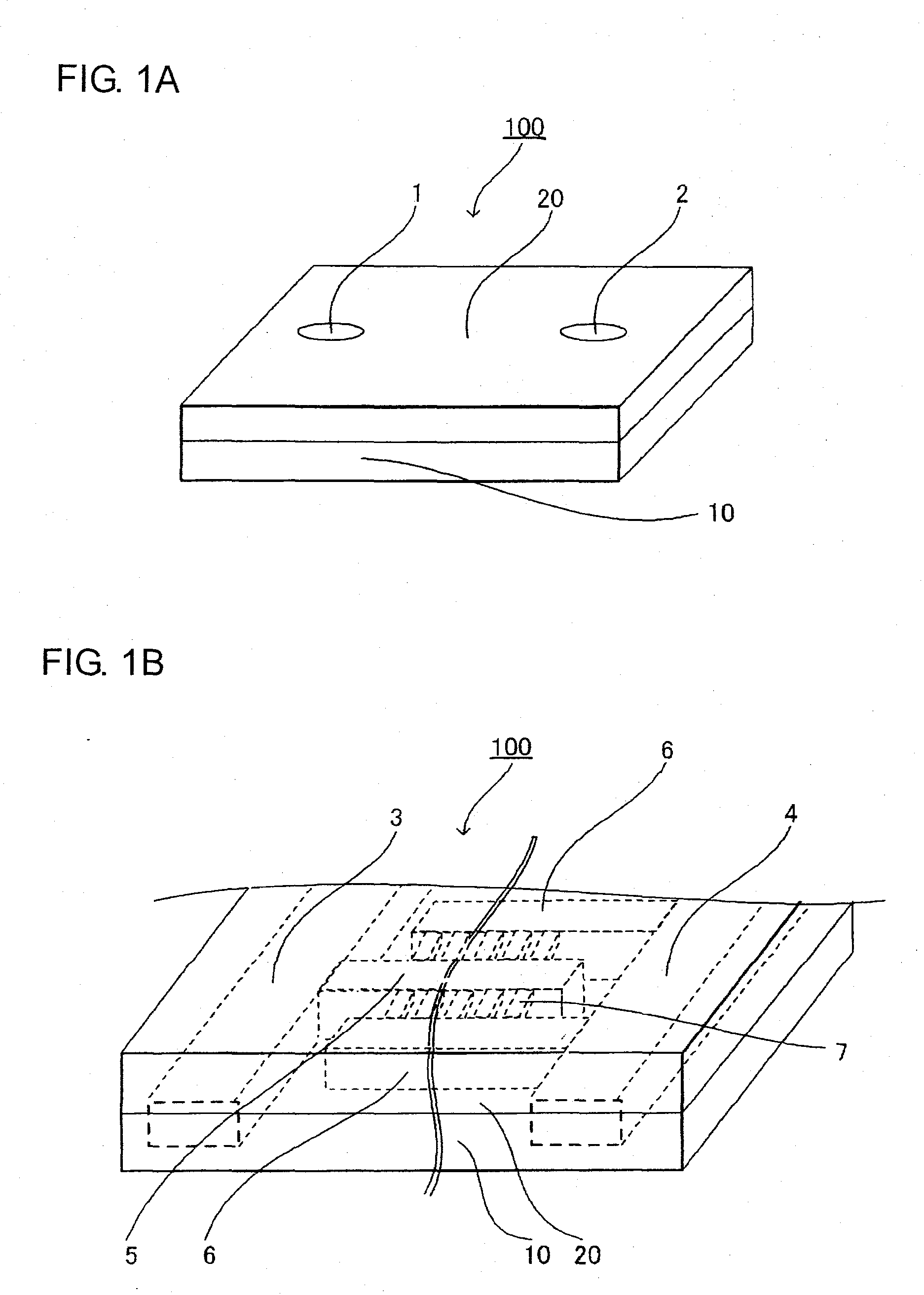
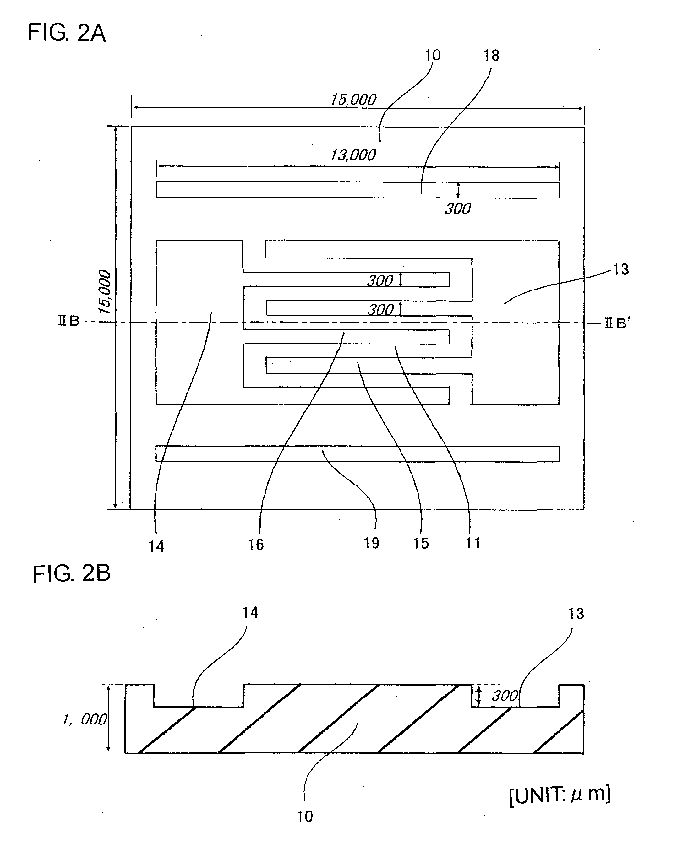
A microchannel array, a method of manufacturing the same, and a blood test method. The microchannel array is formed by joining first and second substrates, each including a fluid inlet and outlet on their surfaces. An internal space structure connects the fluid inlet and outlet, and includes an upstream flow channel connected with the fluid inlet, a downstream flow channel connected with the fluid outlet with a gap therebetween, and a micro flow channel connecting the upstream and downstream flow channels. A minimum distance from a center of a sectional surface of the micro flow channel to a side wall of the micro flow channel is smaller than that of the upstream and downstream flow channels. Each surface of the first and second substrates includes grooves for creating the upstream and downstream flow channels, and the surface of the second substrate has grooves for creating the micro flow channel.

Description

TECHNICAL FIELD[0001]The present invention relates to a microchannel array, a method of manufacturing the same, and a blood test method using the same.BACKGROUND ART[0002]As societies mature, values on medical care and health have changed, and people now seek the “healthy and high-quality life”, not merely the primary health care in a narrow range. It is expected that more and more individuals will place a higher value on preventive medicine than on curative medicine because of an increase in medical care costs, a fact that disease prevention is less costly than treatment, and an increase in the number of those who are in between healthy and diseased.[0003]On this account, in the medical field, particularly in the clinical laboratory field, there is an increasing need for a non-restraint examination system that enables prompt examination and diagnosis in close proximity to a patient such as at an operating room, bedside and home, and for a noninvasive or minimally invasive examinati...

Claims


Application Information

Patent Timeline
IPC IPC(8): C40B30/10C40B40/00C40B50/00
CPCB01L3/502707B01L3/502746G01N33/80B01L2300/0816G01N33/56972B01L2300/0681G01N35/08G01N35/00G01N27/414G01N37/00
Inventor NISHI, TAIJIFUKUDA, MOTOHIROTAZAKI, GOKANAI, SEIICHIKITANI, TAKENORIFUKUHARA, NAOTO
Owner KURARAY CO LTD
Learn More