Electronic device and method

a technology of electronic devices and methods, applied in the direction of basic electric elements, electrical equipment, conductive materials, etc., can solve the problems of inability to meet the needs of the user, etc., and achieve the effect of reducing the number of devices

Active Publication Date: 2009-06-04
GENERAL ELECTRIC CO
View PDF34 Cites 11 Cited by
  • Summary
  • Abstract
  • Description
  • Claims
  • Application Information

AI Technical Summary

Benefits of technology

[0009]In one embodiment, an article is provided that includes a plurality of layers. Each layer includes a sinterable mass having a sinter temperature that is less than about 1000 degrees Celsius, and an inner electrode proximate to the sinterable mass. The inner electrode includes a material having a melting point that is within a determined temperature range of about 10 degrees Celsius to about 200 degrees Celsius above the sintering temperature.
[0010]In one embodiment, an article is provided that includes a plurality of layers. Each layer includes a sinterable mass having a sinter temperature that is less than about 1000 degrees Celsius, and an inner electrode proximate to the sinterable mass. The inner electrode includes a material having a melting point that is within a determined temperature range of about 10 degrees Celsius to about 200 degrees Celsius relative to the sintering temperature.

Problems solved by technology

When a small or moderate voltage is applied across the electrodes, only a tiny current flows, caused by reverse leakage through the diode junctions.
If a transient pulse (often measured in joules) is too high, the device may melt, burn, vaporize, or otherwise be damaged or destroyed.
This unacceptable (catastrophic) failure occurs when “Absolute Maximum Ratings” are exceeded.

Method used


Image

  • Electronic device and method
  • Electronic device and method
  • Electronic device and method

Examples


example 1

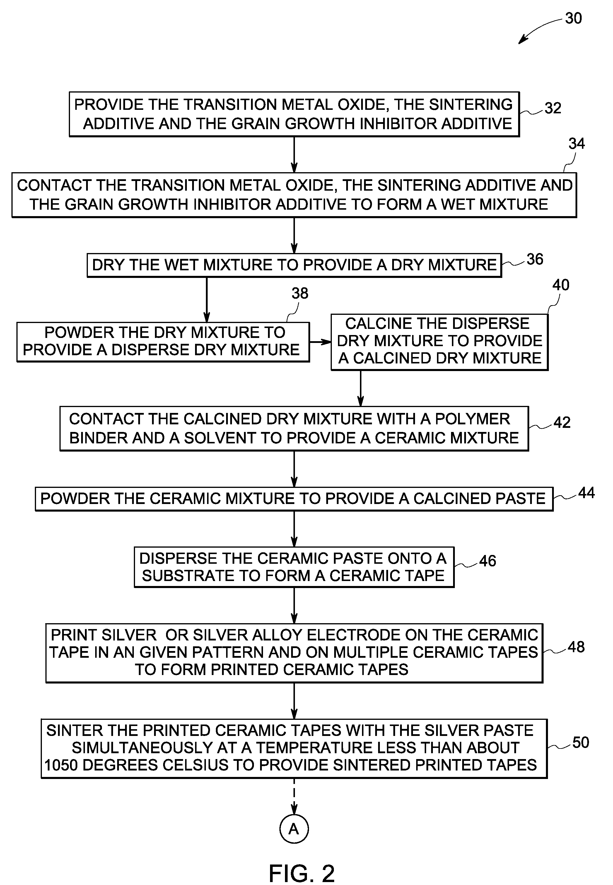
[0071]The transition metal oxide and the additives are weighed to provide a powder mixture as in sample 1. The powder mixture of sample 1 is mixed using a ball mill along with a volatile film-forming polymer binder (polyvinyl alcohol and polyethylene glycol) and solvent (deionized water) to form a ceramic mixture paste. The ceramic mixture is pressed into a green body and the ceramic paste is dispersed onto a smooth surface of a rigid substrate (polyethylene terephthalate) with a release agent. The dispersion is heated to a temperature in a range from about 60 degrees Celsius to about 80 degrees Celsius in order to remove the solvent to form ceramic tapes. Silver paste is screen printed on to the green body and the semi-dry ceramic tapes in a given pattern. The printing is repeated on seven semi-dry ceramic tapes as mentioned above. The tapes are then punched, via filled and stacked together. The printed tapes are laminated with interleaved silver electrodes. The silver printed inte...

example 2

[0072]The transition metal oxide and the additives are weighed to provide a powder mixture as in sample 6. The procedure similar to that described above is employed to make the varistor that includes the sintered mass of sample 6.

example 3

[0073]The transition metal oxide and the additives are weighed to provide a powder mixture as in sample 12. The procedure similar to that described above is employed to make the varistor that includes the sintered mass of sample 12.

Current-Voltage (I-V) Measurement:

[0074]A 10 kiloOhm or 100 MegaOhm resistor 64 is connected in parallel to the varistor 62 and a voltage is applied. V1, the total voltage on sample 66 and varistor is measured using a high voltage probe. V2, the voltage on the resistor is measured by a multimeter. V2 is used to calculate the current flowing through the varistor as given in FIG. 3. V1-V2 is the voltage on the Samples 1-6. To measure I-V curve, at low voltage, a 100 MOhm resistor is used until the voltage on it is higher than about 100 Volts. A 10 kilo Ohm resistor is used to measure the I-V curve under high voltage (higher than about 100 Volts).

[0075]FIG. 4 shows the results of metal oxide varistor materials of Samples 1-3 relative to a commercially availa...


PUM

PropertyMeasurementUnit
temperatureaaaaaaaaaa
melting pointaaaaaaaaaa

Abstract

An article is provided that includes a plurality of layers. Each layer includes a sinterable mass having a sinter temperature that is less than about 1000 degrees Celsius, and an inner electrode proximate to the sinterable mass. The inner electrode includes a material having a melting point that is within a determined temperature range of about 10 degrees Celsius to about 200 degrees Celsius relative to the sintering temperature. A method to make the article is also provided.

Description

RELATED APPLICATIONS[0001]This application is a non-provisional application that claims priority to provisional U.S. Pat. application Ser. No. 60 / 991,871, filed Dec. 3, 2007; the disclosure of which is hereby incorporated by reference.BACKGROUND[0002]1. Technical Field[0003]The invention includes embodiments that relate to an article, for use as a surge protector and / or a varistor. The invention includes embodiments that relate to a method of making and / or using the derived device.[0004]2. Discussion of Art[0005]A varistor is an electronic component with a non-ohmic current-voltage characteristic. Varistors may protect circuits against excessive transient voltages by incorporating them into the circuit in such a way that, when triggered, they will shunt the current created by the high voltage away from the sensitive components. A varistor may be known as Voltage Dependent Resistor or VDR.[0006]A type of varistor is the Metal Oxide Varistor (MOV). This contains a ceramic mass of zinc...

Claims


Application Information

Patent Timeline
Patent Type & Authority Applications(United States)
IPC IPC(8): H01C7/10H01C17/00
CPCB32B18/00Y10T428/2991C04B35/62685C04B2235/3203C04B2235/3206C04B2235/3208C04B2235/3217C04B2235/3241C04B2235/3262C04B2235/3265C04B2235/3272C04B2235/3275C04B2235/3277C04B2235/3279C04B2235/3284C04B2235/3293C04B2235/3294C04B2235/3298C04B2235/3418C04B2235/6025C04B2235/606C04B2235/656C04B2235/6562C04B2235/6567C04B2235/668C04B2235/77C04B2235/785C04B2235/85C04B2237/34C04B2237/62H01C7/1006H01C7/18H01C17/065Y10T29/49082Y10T428/25C04B35/453
Inventor TAN, DANIEL QIIRWIN, PATRICIA CHAPMANYOUNSI, ABDELKRIM
Owner GENERAL ELECTRIC CO
Why Eureka
Try Eureka