
Wireless communication apparatus, power amplifier control method, and power amplifier control apparatus

a technology of power amplifiers and control methods, applied in the direction of gain control, transmission, sustainable buildings, etc., can solve the problems of saturating a low noise amplifier, leaking a transmission signal to the reception unit, and becoming more difficult to secure isolation, so as to prevent a current leakage, correct switching off, and higher gate voltage

Active Publication Date: 2009-05-28
FUJITSU LTD
View PDF5 Cites 14 Cited by
  • Summary
  • Abstract
  • Description
  • Claims
  • Application Information

AI Technical Summary

Benefits of technology

[0011]The present invention aims at realizing control of quickly switching on / off the power amplifier in a simple method on the wireless transmission / reception device in the time division duplex system to effectively suppress a leak of a current from a transmission unit to a reception unit, thereby preventing interference by the leak of the current and improving the power efficiency.
[0013]The wireless communication apparatus switches off the drain power supply of the transmitting power amplifier (power amplifier) during reception in the time division duplex system, and sets a higher gate voltage value than during transmission. By setting a higher gate voltage value during reception than during transmission, the power amplifying device can be switched off more correctly during reception, a leak of a current from the transmission unit to the reception unit can be prevented, and the power amplifying device can be quickly switched on / off.
[0015]The wireless communication apparatus prevents a leak from the transmission unit to the reception unit by switching off the drain power supply of at least the power amplifying unit closest to the antenna in the multi-stage power amplifying unit during reception in the time division duplex system. Furthermore, when the drain power supply switched off during reception is switched on, the switch on is performed sequentially from the power amplifying unit farthest from the antenna, and the timing of switching on the drain power supply of the power amplifying unit closest to the antenna is made to match the timing of switching from reception to transmission. While matching the rising timing for each power amplifying unit by changing the timing of switching on depending on the capacity of each power amplifying device, the power amplifying unit closest to the antenna is switched on with the timing of the transmission / reception switch, whereby preventing a leak of current from the transmission unit to the reception unit, and realizing the quick on / off switch of power amplifying devices.
[0016]The control signal generation unit can further generate a gate voltage control signal for control of a gate voltage of the power amplifying unit, and the power amplifying unit can set a higher gate voltage during reception in the time division duplex system than during transmission. By setting a higher gate voltage value during reception than during transmission, the power amplifying device can be more correctly switched off, thereby quickly switching on / off the power amplifying device.
[0017]The disclosed wireless communication apparatus can quickly switch on and off the power amplifying device, and a leak of current from the transmission unit to the reception unit can be effectively suppressed. By suppressing the leak of current to the reception unit, the interference by the leak of current can be prevented, and the power efficiency can be improved.

Problems solved by technology

When the isolation is not sufficient, there occur problems such as a leak of a transmission signal to the reception unit, saturating a low noise amplifier, etc.
Then, with a shorter transmission / reception switch time, it becomes more difficult to secure the isolation.
Therefore, the residual signal is leaked to the reception side, thereby possible degrading the reception performance.
However, as described above, since the current passing through the drain of the power amplifier is large, it is not easy to quickly switch on / off the power amplifier by the switch circuit.

Method used


Image

  • Wireless communication apparatus, power amplifier control method, and power amplifier control apparatus
  • Wireless communication apparatus, power amplifier control method, and power amplifier control apparatus
  • Wireless communication apparatus, power amplifier control method, and power amplifier control apparatus

Examples


Embodiment Construction

[0028]The preferred embodiments of the present invention are described below in detail with reference to the attached drawings.

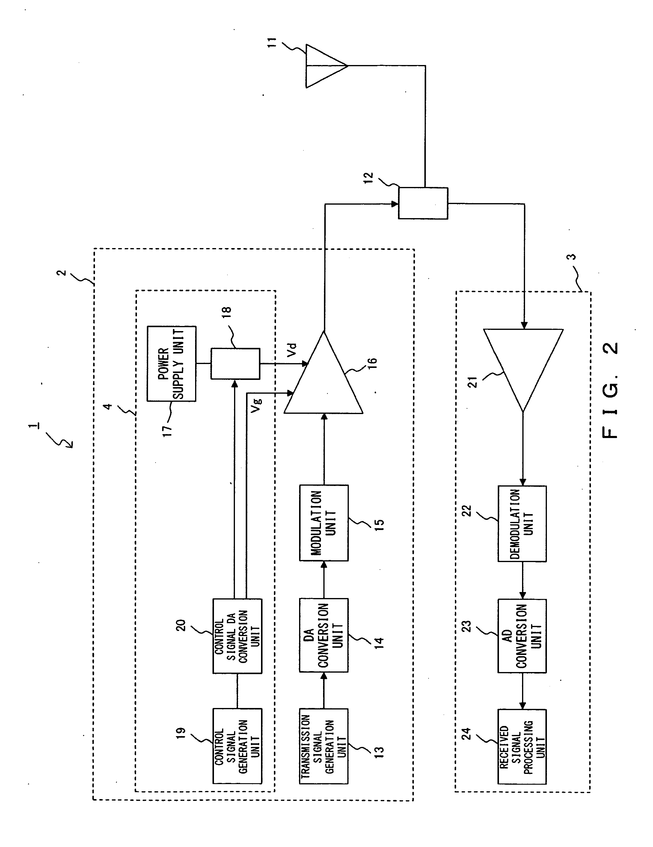
[0029]FIG. 2 shows the configuration of the wireless transmitter / receiver according to the first embodiment. A wireless transmitter / receiver 1 shown in FIG. 2 is provided for a terminal device in the TDD system, and is configured by an antenna 11, a transmission / reception switch unit 12, a transmission unit 2, and a reception unit 3.

[0030]The transmission unit 2 is configured by a transmission signal generation unit 13, a DA conversion unit 14, a modulation unit 15, a power amplifier 16, and a power amplifier control unit 4.

[0031]In the configuration of the transmission unit 2, the antenna 11 transmits a signal from the wireless transmitter / receiver 1 and is addressed to a base station or a terminal device of a communication partner, and receives a signal transmitted from the base station or the terminal device of the communication partner.

[0032]The transmis...


PUM


Abstract

In a wireless communication apparatus in a time division duplex system, a transmission signal generation unit generates a transmission signal. A power amplifying device amplifies the generated transmission signal. A control signal generation device generates a drain voltage control signal for control of the drain voltage of the power amplifying device, and a gate voltage control signal for control of the gate voltage of the power amplifying device. The switch unit switches off the drain power supply of the power amplifying device during reception in the time division duplex system according to the drain voltage control signal. In addition, the power amplifying device sets a higher gate voltage during reception in the time division duplex system higher than during transmission according to the gate voltage control signal.

Description

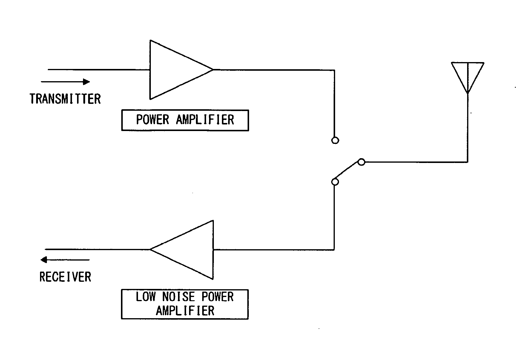
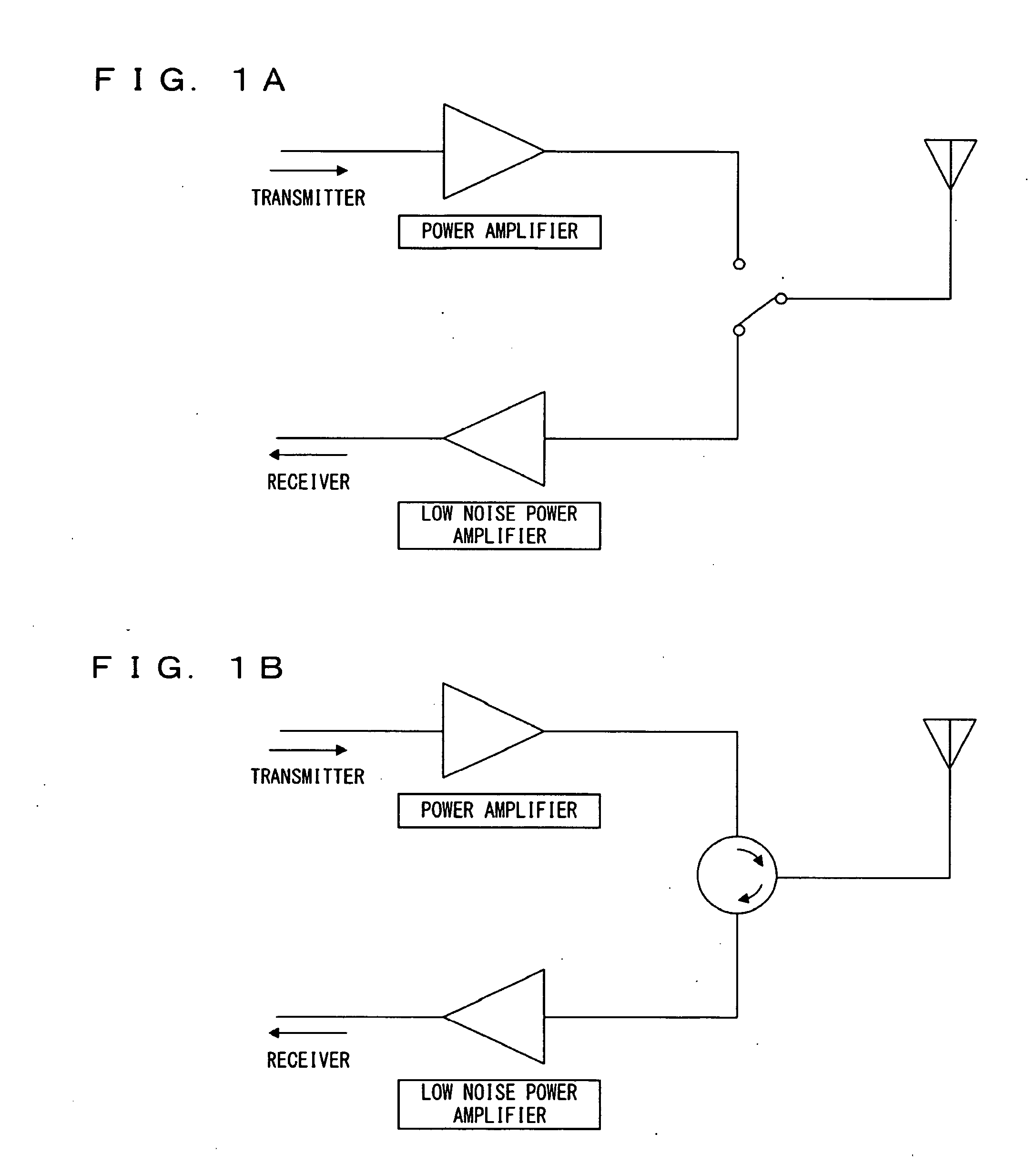
BACKGROUND OF THE INVENTION[0001]1. Field of the Invention[0002]The present invention relates to the technology of controlling a power amplifier, and more specifically to a power amplifier used in a wireless transmission / reception device in a time division duplex system.[0003]2. Description of the Related Art[0004]In the time division duplex system (hereinafter referred to as TDD for short), a communication path is divided by a time axis, a transmission / reception switch is quickly made, and a frequency band is shared between a transmitter and a receiver. As shown in FIGS. 1A and 1B, a switch and a circulator are provided immediately below an antenna so that communications can be performed by switching between transmission and reception.[0005]In the TDD system, a frequency band is shared between transmission and reception. Therefore, it is necessary that isolation is completely secured between a transmission unit and a reception unit. When the isolation is not sufficient, there occur...

Claims


Application Information

Patent Timeline
Patent Type & Authority Applications(United States)
IPC IPC(8): H04B1/04
CPCH04B1/04Y02B60/50H04B1/44
Inventor HONDA, ATSUSHIYOKOO, KAORUOISHI, YASUYUKIOHASHI, YOJI
Owner FUJITSU LTD
Learn More