
Communication Device

a communication device and communication channel technology, applied in the direction of transmission monitoring, amplitude demodulation, orthogonal multiplex, etc., can solve the problems of complex construction and processing of propagation channel distortion compensation, heavy load on communication device processing, and difficulty in applying communication device to an actual operating system, so as to prevent overflow or digit loss, the effect of sufficient dynamic rang

Inactive Publication Date: 2009-05-28
KOKUSA ELECTRIC CO LTD
View PDF9 Cites 4 Cited by
  • Summary
  • Abstract
  • Description
  • Claims
  • Application Information

AI Technical Summary

Benefits of technology

[0019]The present invention has been made in view of this circumstance in the related art. An object of the present invention is to provide a communication device capable of performing propagation channel distortion compensation by a simple construction and a simple processing.
[0054]Thus, when the effective word length is increased through the conversion / reconversion of the digitalized received signal, bits are shifted to prevent overflow or digit loss and hence the dynamic range provided by the word length can be effectively used. Thus, it is possible to ensure a dynamic range sufficient for the communication system.

Problems solved by technology

However, in the communication device for performing the above-mentioned propagation channel distortion compensation shown in FIG. 7, the construction and processing for performing the propagation channel distortion compensation become very complicated and hence the processing of placing a heavy load on the communication device is required.
Thus, even if the communication device is expected to achieve an improvement in characteristics, it is actually difficult to apply the communication device to an actually operated system.

Method used


Image

  • Communication Device
  • Communication Device
  • Communication Device

Examples


Embodiment Construction

[0070]Embodiments according to the present invention will be described with reference to the drawings.

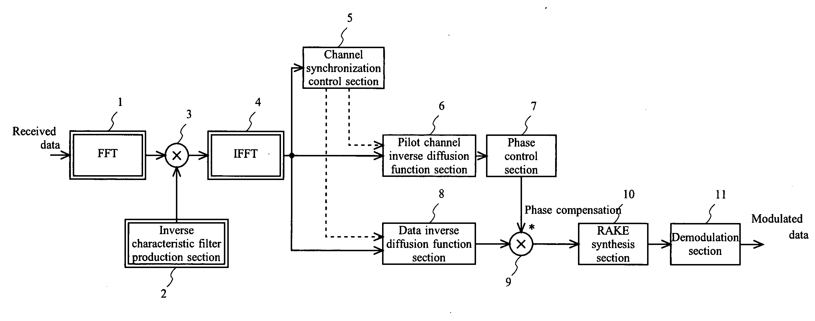
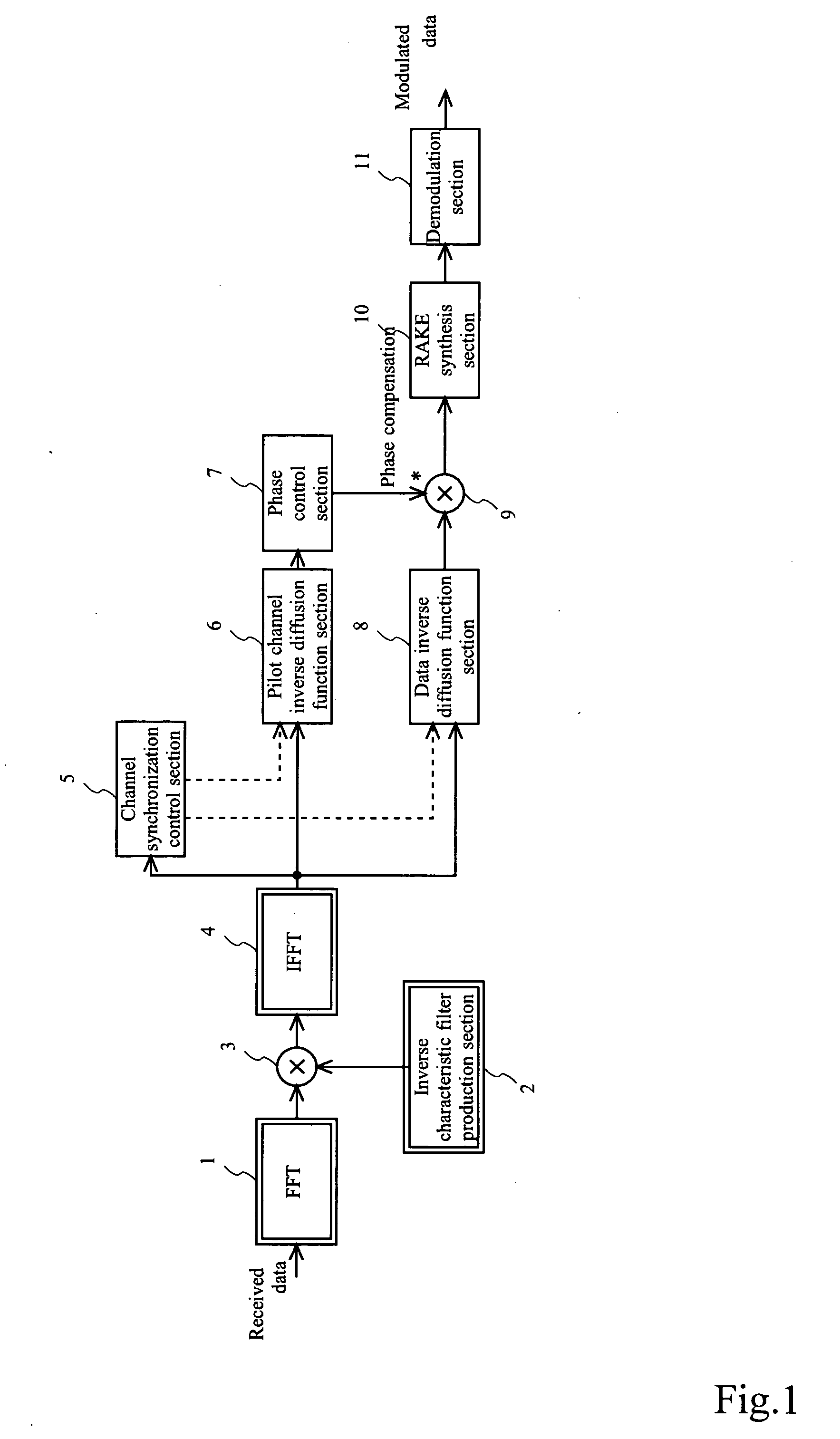
[0071]In FIG. 1 is shown a construction example of a receiver as a construction example of a W-CDMA base station device for performing propagation channel distortion compensation according to one embodiment of the present invention.

[0072]The W-CDMA base station device of this embodiment includes: a fast Fourier transform (FFT) section 1; a inverse characteristic filter production section 2; a multiplier 3; an inverse fast Fourier transform (Inverse FFT) section 4; a channel synchronization control section 5; a pilot channel inverse diffusion function section 6; a phase control section 7; a data inverse diffusion function section 8; a multiplier 9; a RAKE synthesis section 10; and a demodulation section 11.

[0073]Here, the function sections added so as to compensate distortion in the propagation channel, in this example, are the FFT section 1, the inverse characteristic filter product...


PUM


Abstract

In a communication device for receiving signals from devices that become communication partners, received signals from the respective devices are identified. Each of the devices that become communication partners is provided with a frequency spectrum of a pattern specific to each of the devices. In the communication device, storage means stores correspondence between information identifying the devices that become communication partners and the frequency spectrums provided to the respective devices, acquisition means acquires a frequency spectrum contained in a received signal, identification means compares the frequency spectrum acquired by the acquisition means with the frequency spectrums stored by the storage means to identify a device corresponding to the frequency spectrum that coincides with the frequency spectrum acquired by the acquisition means and which is stored by the storage means.

Description

TECHNICAL FIELD[0001]The present invention relates to a communication device for receiving a signal through a propagation channel and, in particular, to a communication device for compensating distortion in a propagation channel by a simple construction or a simple processing.[0002]In addition, the present invention relates to an effective technology for identifying a received signal of each of plural other communication devices when receiving signals from the plural other communication devices.BACKGROUND ART[0003]For example, it has been well known that when the wireless transfer function of expressing distortion in a wireless propagation channel can be extracted, the function of its inverse characteristics can be produced to be able to cancel characteristic degradation in the wireless propagation channel with large effect. However, a processing capacity required to find the wireless transfer function is high, so that it is difficult to realize the wireless transfer function in an ...

Claims


Application Information

Patent Timeline
IPC IPC(8): H04L27/06H04B17/00H04B1/707H04B1/7107H04L27/01H04W28/18H04W72/04
CPCH04L5/0016H04L5/0048H04L2025/03414H04L25/03159H04L27/2614H04L25/0228H03M1/18H04L27/00
Inventor YOTSUMOTO, KOJI
Owner KOKUSA ELECTRIC CO LTD
Learn More