
Collapsible door panel support structures and methods of assembly

a support structure and door panel technology, applied in the field of collapsible door panel structures, can solve the problems of collapsible feature and reduce and achieve the effect of reducing the lateral stiffness of the door trim subsystem

Inactive Publication Date: 2009-05-28
FORD GLOBAL TECH LLC
View PDF6 Cites 24 Cited by
  • Summary
  • Abstract
  • Description
  • Claims
  • Application Information

AI Technical Summary

Benefits of technology

[0004]The present invention provides an alternative arrangement to known vehicle door handle and pull cup and support structure designs. According to the present invention, a collapsible door support structure is provided with a pre-defined bend feature. According to this design, the deformation of the door inner panel is used to bend the armrest substrate prior to interaction with the occupant. If there is no impact, the shape of the armrest structure provides for a stiff structure which will aid in passing durability requirements.
[0006]In the event of an impact upon the vehicle door, the door inner sheet metal panel is pushed horizontally in a direction that is vehicle inward. The collapsible feature of the structure formed between the door inner sheet metal and the door trim panel causes the horizontal movement to be translated into vertical or upward movement and transmitting the energy away from the vehicle occupant, thus avoiding the door trim panel from being pushed inward into the passenger area of the vehicle. The collapsible feature also reduces the lateral stiffness of the door trim subsystem.

Problems solved by technology

The collapsible feature also reduces the lateral stiffness of the door trim subsystem.

Method used


Image

  • Collapsible door panel support structures and methods of assembly
  • Collapsible door panel support structures and methods of assembly
  • Collapsible door panel support structures and methods of assembly

Examples


Embodiment Construction

[0027]In the following figures, the same reference numerals will be used to refer to the same components. In the following description, various operating parameters and components are described for different constructed embodiments. These specific parameters and components are included as examples and are not meant to be limiting.

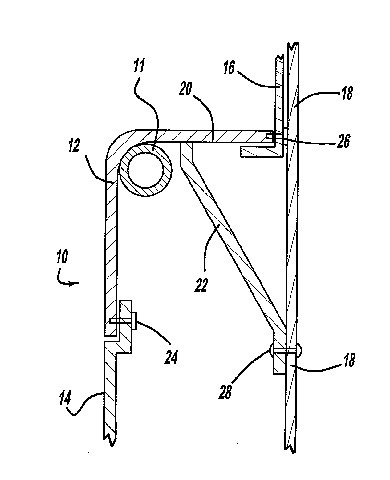
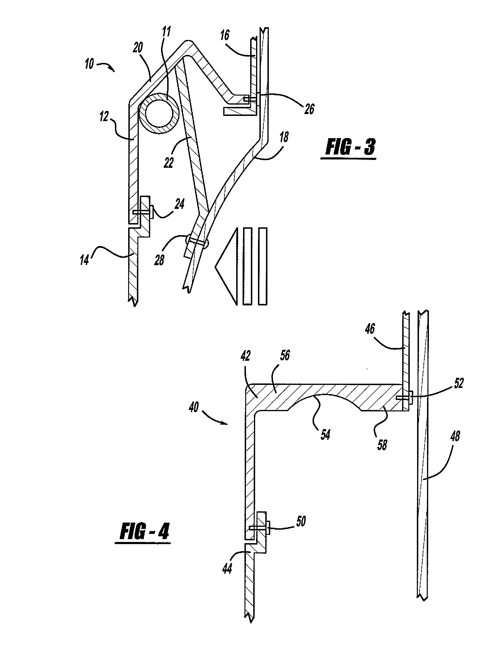
[0028]With reference to FIG. 1, a system using a bracket in relation to a collapsible door handle is shown. In addition, FIG. 2 and FIG. 3 illustrate two stages of impact advancement on the vehicle door.

[0029]More particularly, a sectional view of a door sub-assembly, generally illustrated as 10, is shown. The door sub-assembly 10 includes a door handle 11, a door armrest 12, a lower door trim panel 14, an upper door trim panel 16, and a door inner sheet metal 18. The door armrest 12 includes a bend feature 20 formed into the door armrest 12. A bracket 22 is provided between the door inner sheet metal 18 and the door armrest 12 at an area just adjacent to t...


PUM


Abstract

A collapsible door support structure includes a pre-defined bend or local stiffening feature. The collapsible structure is either be incorporated into the door handle or is incorporated into a bracket that is either attached to the door handle or to the door pull cup. If in the form of a bracket, at least one end of the bracket is attached to the door inner sheet metal. The other end of the bracket may be attached to the door handle or to the door trim panel. If used as a door pull cup support bracket a portion of the bracket is fixed to the bracket. In the event of an impact upon the vehicle door, the door inner sheet metal panel is pushed horizontally in a direction that is vehicle inward. The collapsible feature of the structure formed between the door inner sheet metal and the door trim panel causes the horizontal movement to be translated into vertical or upward movement and transmitting the energy away from the vehicle occupant, thus avoiding the door trim panel from being pushed inward into the passenger area of the vehicle.

Description

TECHNICAL FIELD[0001]The present invention relates generally to collapsible door panel structures for use with vehicle doors. More particularly, the present invention relates to collapsible door panel structures for use with the door handle and the pull cup of an armrest. The collapsible door panel support structures are strong and durable under normal use but demonstrate compromised lateral stiffness in the event of a side impact.BACKGROUND OF THE INVENTION[0002]Side impact events in vehicles have been identified as one of the top priorities for both research and regulation with government requirements continuing to become more stringent. These additional requirements make designs for door trim systems more challenging because the occupants may impact the door trim at the pull cup or grab handle. It is known in vehicles to provide an armrest in a door typically having an integrated pull cup to allow the occupant to pull the door shut. According to the known arrangement, the pull cu...

Claims


Application Information

Patent Timeline
Patent Type & Authority Applications(United States)
IPC IPC(8): B60J5/00
CPCB60J5/0434
Inventor HALL, IAN BREWSTERSPAHN, BRIAN ROBERTPINKERTON, JOHNJAYASURIYA, MANGALA M.
Owner FORD GLOBAL TECH LLC
Learn More