
Flat container comprising thermoplastic resin and method for molding the same

a thermoplastic resin and container technology, applied in the direction of synthetic resin layered products, transportation and packaging, other domestic articles, etc., can solve the problem of exerting an adverse effect on stretch molding

Active Publication Date: 2009-05-21
TOYO SEIKAN GRP HLDG LTD
View PDF3 Cites 8 Cited by
  • Summary
  • Abstract
  • Description
  • Claims
  • Application Information

AI Technical Summary

Benefits of technology

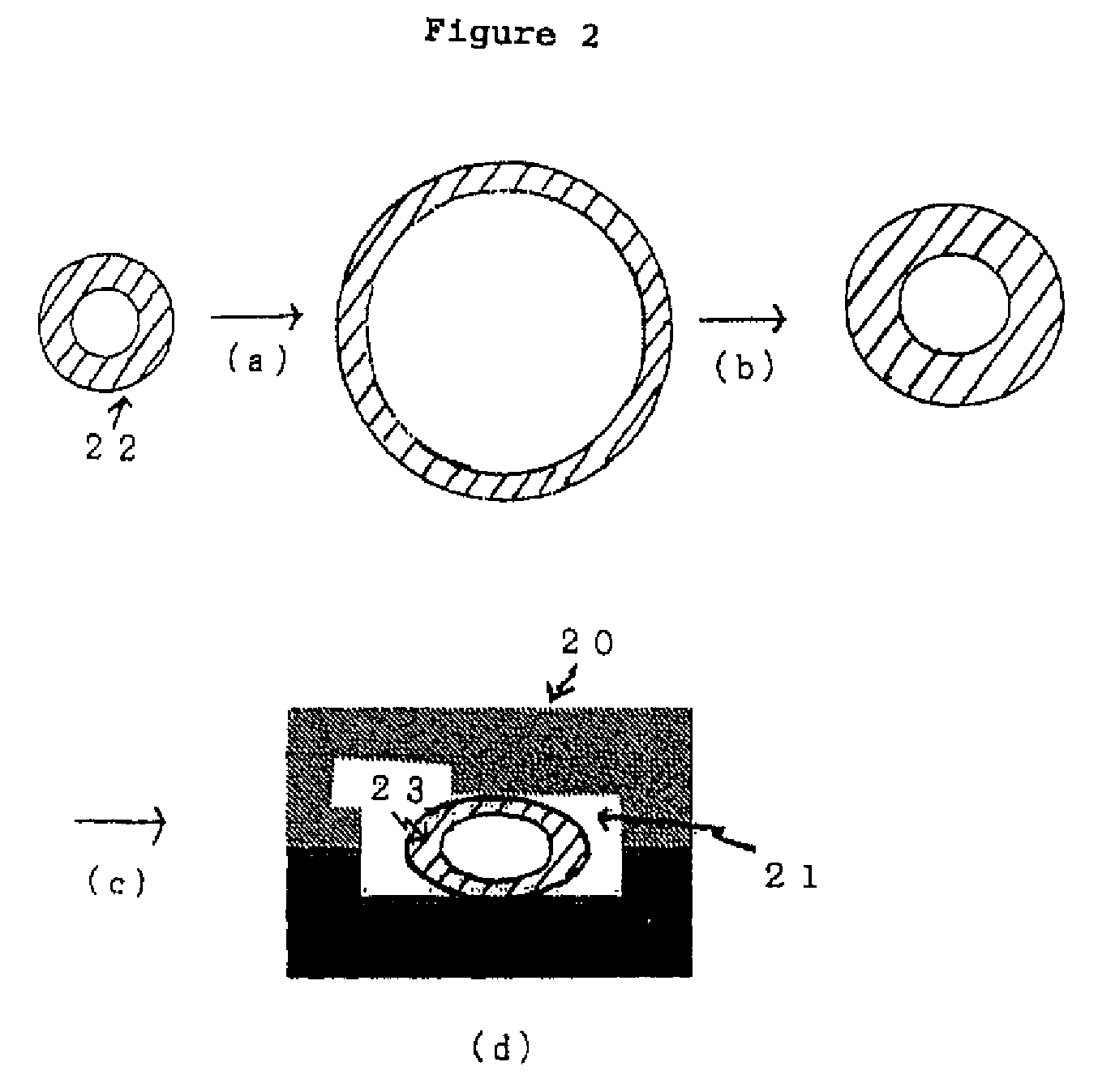
[0016]Incidentally, Japanese Patent Publication No. 59-53861 described above discloses a method for obtaining a flat container that involves inflating a bottomed parison having a circular section in a first blow mold into an intermediate molded article, inserting this intermediate molded article into a second blow mold, flattening the intermediate molded article into an elliptical shape by mold closing, and then performing blow molding. Under this method, as can be seen in Figure (C) of this document, an intermediate molded article 7 is depressed by mold closing, whereby also the major axis portion of the intermediate molded article 7 is brought into close contact with the mold. On the other hand, in the above-described prior inventions, a parison is subjected to primary blow molding and molded into a bottomed cylindrical body having a diameter larger than the minor axis of a mold for secondary blow molding, the bottomed cylindrical body is then caused to shrink in a heated condition, whereby the bottomed cylindrical body is caused to maintain a diameter which is larger than the minor axis of a cavity within the mold for secondary blow molding, the bottomed cylindrical molded article is then attached to the interior of the mold for secondary blow molding. And as shown in (d) of FIG. 2, mold clamping is performed, with the bottomed cylindrical molded article depressed in a flat condition in the minor axis direction of the cavity within the mold for secondary blow molding, so that the major axis portion of the bottomed cylindrical body does not come into contact with mold surfaces. The prior inventions differ from the invention of this document in the two points of shrinkage under heat and mold clamping performed so that the major axis portion does not come into contact with mold surfaces. Thanks to these differences, in the prior inventions, the wall thickness is sufficiently made uniform and mechanical strength and heat resistance are improved.
[0019]On the basis of these recognitions, the inventors of the present application arrived at the constituent features: (1) by subjecting an upper portion and / or a lower portion of a body molding surface of the mold for blow molding at least on the long-side side of a container to mold surface treatment, the slipperiness of a resin material on a partial surface of the mold for blow molding is improved, and as a result of this, further uniformity of the wall thickness of the container is achieved; and (2) by forming one or more convexities, which are horizontal as viewed from the height of a container, in an upper portion and / or a lower portion of a body molding surface in the mold for blow molding at least on the long-side side of the container, the waviness of concavities which partially occurs on the major axis side surface of an intermediate molded article is caused to be absorbed in the convexities and removed, and in a case where minor wrinkles incapable of being completely removed tend to remain, by stretching the wrinkles during secondary blow molding, the prevention of the occurrence of wrinkles on the surface is realized. Thus the present inventors found out the constituent features as the second basic invention of the present application. Furthermore, by combining the features (1) and (2), the occurrence of concavities and wrinkles can be suppressed more as the feature (3).
[0020]Incidentally, as the feature (4), in the body of the product container on the major axis side, transverse (horizontal) concave ribs (cross beams of grooves) are formed by convexities on the blow mold surface as shown in FIG. 7, and it has become possible to form a flat container with transverse ribs that has remarkable uniformity of wall thickness and is excellent in mechanical strength and heat resistance.
[0030][8] The flat polyester resin container according to any one of [1] to [6], which is characterized in that the flat polyester resin container is obtained by subjecting a bottomed parison preformed from a polyester resin to primary blow molding, thereby molding the bottomed parison into a bottomed cylindrical body having a diameter larger than the minor axis of a cavity within a mold for secondary blow molding, thereafter causing the bottomed cylindrical body to shrink in a heated condition, thereby to cause the bottomed cylindrical body to maintain a diameter which is smaller than the major axis of the cavity within the mold for secondary blow molding and larger than the minor axis thereof, attaching the bottomed cylindrical molded article to the interior of the mold for secondary blow molding, performing mold clamping, with the bottomed cylindrical molded article depressed in the minor axis direction of the cavity within the mold, feeding thereafter a pressure fluid into the bottomed cylindrical molded article, and causing the bottomed cylindrical molded article to flow in a heated condition along the shape of the cavity on an inner surface of the mold, thereby to mold the flat polyester resin container.
[0039][17] A method for manufacturing a flat container by the two-stage blow molding process, which is characterized in that the method comprises subjecting a bottomed parison preformed from a polyester resin to primary blow molding, thereby molding the bottomed parison into a bottomed cylindrical body having a diameter larger than the minor axis of a cavity within a mold for secondary blow molding, thereafter causing the bottomed cylindrical body to shrink in a heated condition, thereby to cause the bottomed cylindrical body to maintain a diameter which is smaller than the major axis of the cavity within the mold for secondary blow molding and larger than the minor axis thereof, attaching the bottomed cylindrical molded article to the interior of the mold for secondary blow molding, performing mold clamping, with the bottomed cylindrical molded article depressed in the minor axis direction of the cavity within the mold, then feeding a pressure fluid into the bottomed cylindrical molded article, and causing the bottomed cylindrical molded article to flow in a heated condition along the shape of the cavity on an inner surface of the mold, thereby to mold the flat container.

Problems solved by technology

This causes the phenomenon that a desired amount of resin is not supplied for the stretch molding on the major axis side requiring a large magnification of elongation, thereby exerting an adverse effect on stretch molding.

Method used


Image

  • Flat container comprising thermoplastic resin and method for molding the same
  • Flat container comprising thermoplastic resin and method for molding the same
  • Flat container comprising thermoplastic resin and method for molding the same

Examples


embodiment 1

[0131]A bottomed parison, which was a first intermediate molded article having an outside diameter of 22 mm, a thickness of 3.4 mm and a height of 80 mm, was preformed from commercially available polyethylene terephthalate (PET), heated air was blown in by free blowing and the first intermediate molded article was subjected to primary blow molding to form a second intermediate molded article having an outside diameter of 90 mm.

[0132]The second intermediate molded article subjected to the primary blow molding was caused to shrink and be fixed for 8 seconds in an oven at 600° C. and a shrunk, molded article having an outside diameter of 60 mm, which was a third intermediate molded article, was obtained.

[0133]A mold for second blow molding (set at 140° C.) had a cavity (section: minor axis 50 m, major axis 66 mm) with the rectangular section shown in (d) of FIG. 2, and an upper portion of a body molding surface of the blow mold on the long-side side of a container was coated with a flu...

embodiment 2

[0136]A flat container having an elliptical section and a flatness ratio of 1.5 was molded in the same way as in Embodiment 1, with the exception that primary blow molding was performed by using a mold for primary blow molding instead of performing free blow molding and that a mold which upper portion of a body molding surface thereof on the long-side side (major axis side) of a container was coated with a fluororesin and which had a cavity (section: minor axis 47 mm, major axis 70 mm) with an elliptical section was used as a second blow mold.

embodiment 3

[0137]A flat container having a rectangular section and a flatness ratio of 2.0 was molded in the same way as in Embodiment 1, with the exception that primary blow molding was performed by using a mold for primary blow molding instead of performing free blow molding and that a mold which upper portion of a body molding surface thereof on the long-side side of a container was coated with a fluororesin and which had a cavity (section: minor axis 40 mm, major axis 80 mm) with a rectangular section was used as a second blow mold.


PUM

PropertyMeasurementUnit
elongationaaaaaaaaaa
temperaturesaaaaaaaaaa

Abstract

The invention realizes easy manufacturing of a flat container molded by blow molding, in which the wall thickness of a container wall is made uniform, and which provides improved mechanical strength, heat resistance, etc. and has a good appearance.The flat container obtained by the blow molding of a polyester resin is characterized in that the container has a flatness ratio of not less than 1.3, and in that its body has a wall thickness ratio of a maximum wall thickness to a minimum wall thickness of not more than 1.6, a difference in elongation between a maximally stretched portion and a minimally stretched portion of not more than 150% in a tensile test at 95° C., a crystallinity of not less than 30%, and a difference in TMA non-load change between a maximally stretched portion and a minimally stretched portion of not more than 500 μm at 75° C. and 100° C.

Description

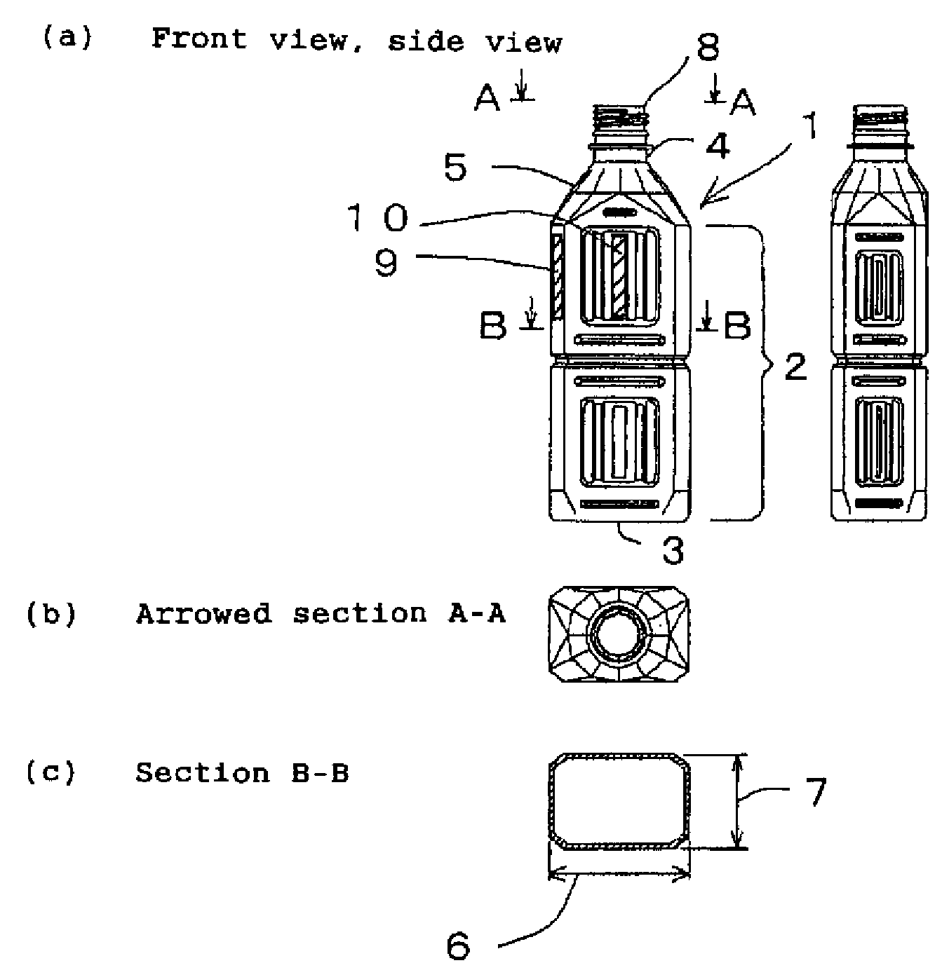
TECHNICAL FIELD[0001]The present invention relates to a flat container made of a thermoplastic resin and, more particularly, to a flat container whose section is an ellipse or a rectangle or has other shapes, the body of which has a uniformly formed wall thickness, and which has high thermal resistance and is not deformed at high temperatures and a method for molding the flat container.BACKGROUND ART[0002]Thanks to their excellent mechanical strength, moldability, transparency, recyclability of resources, etc. polyester resin containers, such as PET bottles, have been recognized as containers for food and drink and they have been in great demand. In particular, recently polyester resin containers have been habitually used by consumers as portable small containers for beverage use. The heat resistance and pressure resistance of such small containers for beverage use have been remarkably improved by the development of the two-stage blow molding process (refer to Japanese Patent Public...

Claims


Application Information

Patent Timeline
Patent Type & Authority Applications(United States)
IPC IPC(8): B65D1/02
CPCB29B2911/14053Y10T428/1303B29B2911/1408B29B2911/14093B29B2911/14113B29B2911/1412B29B2911/1414B29B2911/14146B29B2911/14166B29B2911/14173B29B2911/1444B29B2911/14466B29B2911/14593B29B2911/14653B29B2911/14713B29B2911/14926B29C49/0073B29C49/04B29C49/06B29C49/18B29C49/4242B29K2067/00B29K2995/0041B29K2995/0043B29K2995/0077B29L2031/7158B65D1/0215B65D1/0223B65D2501/0018B65D2501/0036B65D2501/0081B29C37/0067B29K2067/003B29K2995/0097B29C49/22Y10T428/139Y10T428/1359Y10T428/13Y10T428/1352B29B2911/14066B29C2949/3016B29C2949/302B29C2949/3008B29C2949/3012B29C2949/3026B29C2949/3036B29C2949/3034B29C2949/3028B29C2949/3044B29C2949/3042B29C2949/0777B29C2949/0811B29C2949/0773B29C2949/082B29C2949/0829B29C2949/0865B29C49/071B29C49/42832B29C2949/0715B29C49/6605B29C2049/7831B29C49/087B29C2049/7879B65D1/02B29C49/48B29C2049/4874B29L2031/712
Inventor KOMIYA, ATSUSHIHONDA, HIROYUKIFUJIKAWA, TAKUYAMOROFUJI, AKIHIKO
Owner TOYO SEIKAN GRP HLDG LTD
Learn More