
Method of brazing a first metal member to a second metal member using a high wettability metal as layer between the two metal members; reformer manufactured by this method, the metal members having grooves

Inactive Publication Date: 2009-05-21
TOYOTA JIDOSHA KK
View PDF17 Cites 10 Cited by
  • Summary
  • Abstract
  • Description
  • Claims
  • Application Information

AI Technical Summary

Benefits of technology

[0007]The present invention provides a method for brazing that reduces the occurrence of poor joining, even under circumstances where oxides are formed during brazing and wettability is reduced in the brazing.
[0012]According to the above-noted method for brazing, before brazing, which is accompanied by heating in the joining step, a high-wettability metal is applied to at least the brazing surface of the first metal member (in the metal application step). In the joining step, the first metal member and the second metal member are joined by brazing, which is accompanied by heating, with brazing filler metal via the pre-applied high-wettability metal. That is, the wettability of the brazing filler metal at the brazing surface is improved, thereby reducing the formation of weak joints.
[0013]By leaving a surface on the first metal member to which the high-wettability metal is not applied, an oxide is formed on the surface when the surface is brazed (in the joining step), and further an oxide covering film is formed thereon to impart superior corrosion resistance to the first metal member.

Problems solved by technology

However, because of the low wettability between alumina and the brazing filler metal, when the brazing filler metal melts on the surface of the alumina layer, the brazing filler metal is repelled, which may cause pores to form at the joint after coagulation of the brazing filler metal, or cracks at the joint, causing partially poor joining.

Method used


Image

  • Method of brazing a first metal member to a second metal member using a high wettability metal as layer between the two metal members; reformer manufactured by this method, the metal members having grooves
  • Method of brazing a first metal member to a second metal member using a high wettability metal as layer between the two metal members; reformer manufactured by this method, the metal members having grooves
  • Method of brazing a first metal member to a second metal member using a high wettability metal as layer between the two metal members; reformer manufactured by this method, the metal members having grooves

Examples


first embodiment

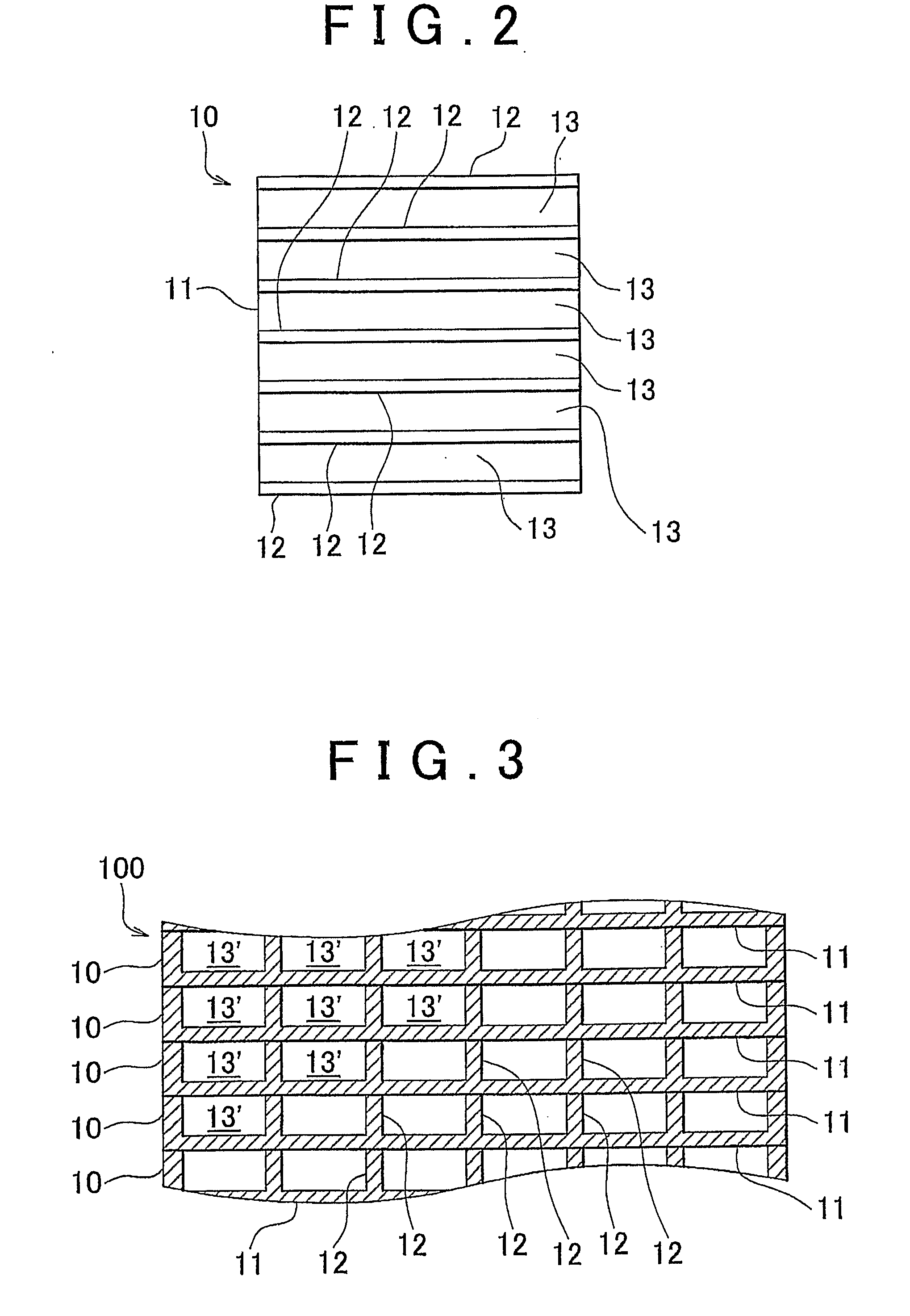
[0050]In the first embodiment, a metal sheet 10 made of stainless steel (Fe-20Cr-5Al; units of wt %) having a plurality of grooves 13 was prepared. In this embodiment, a plurality of metal sheets 10 are stacked in the thickness direction and adjacent metal sheets 10 are joined by brazing to form the catalyst carrier base material (becoming the joined assembly 100) of a stacked fuel reformer. FIG. 2 shows the plan view of the metal sheets 10 forming the catalyst carrier base material of a stacked fuel reformer, and FIG. 3 shows a cross-sectional view, cut along the thickness direction, of a plurality of the metal sheets 10. The metal sheets 10 have a plurality of grooves 13 delineated by the plurality of partition walls 12 on one surface of the bottom sheets 11. The thickness of the bottom sheets 11 and the partition walls 12 were approximately 300 μm. A plurality of the metal sheets 10 are stacked so that the edge surfaces of the partition walls 12 come into contact with the other s...


PUM

PropertyMeasurementUnit
Thicknessaaaaaaaaaa
Thicknessaaaaaaaaaa
Wettabilityaaaaaaaaaa

Abstract

A method for brazing a first metal member, on which an oxide forms during brazing, and a second metal member, in which a high-wettability metal having a wettability with a brazing filler metal that is higher than that of the oxide is applied to at least a brazing surface of the first metal member. The first metal member and the second metal member are then joined by heating the brazing filler metal to melt the brazing filler metal. The oxide covering film is formed on the portion of the surface of the first metal member to which the high-wettability metal was not applied.

Description

BACKGROUND OF THE INVENTION[0001]1. Field of the Invention[0002]The present invention relates to a method for brazing members of the same or different compositions. In particular, it relates to a method for brazing to a metal member having reduced wettability caused by the formation of oxides during the brazing.[0003]2. Description of the Related Art[0004]When brazing members of the same or different composition, a brazing filler metal is applied between the member to be brazed and the receiving member to which the member is to be brazed, after which the members overall are heated or the joining location is heated to the brazing temperature to melt the brazing filler metal and join (braze) the members. Methods of applying the brazing filler metal that are used include, for example, thermal spraying of a brazing filler metal covering film on the brazing surface (refer to Japanese Patent Application Publications No. JP-A-7-108372 and JP-A-62-214865), spot welding to hold a brazing foi...

Claims


Application Information

Patent Timeline
IPC IPC(8): B01J8/02B23K35/22
CPCB23K1/0008B23K1/19B23K1/20B23K2201/045H01M8/0297B23K2201/18B23K2201/34B23K2203/04B23K2201/14B23K2101/045B23K2101/14B23K2101/18B23K2101/34B23K2103/04B23K2103/05Y02E60/50Y02P70/50
Inventor SHIMAZU, TAKASHIKIMURA, KENJI
Owner TOYOTA JIDOSHA KK
Learn More