
Power line transmission

Active Publication Date: 2009-05-21
FRANCE TELECOM SA
View PDF7 Cites 9 Cited by
  • Summary
  • Abstract
  • Description
  • Claims
  • Application Information

AI Technical Summary

Benefits of technology

[0025]The presence of the device, according to an aspect of the disclosure, in an electrical installation therefore prevents disturbance of the transfer function of the transmission channel linked to the presence or absence of certain electrical devices (hairdryer, modem, lamp, computer, etc.) in the socket outlets of the installation, and their operating state (operating or on standby). In other words, the device, according to an aspect of the disclosure, guarantees the stability of the PLT signal transmission channel and consequently prevents transmission errors and improves quality of service.
[0042]increased power consumption by the customer of the electrical installation;
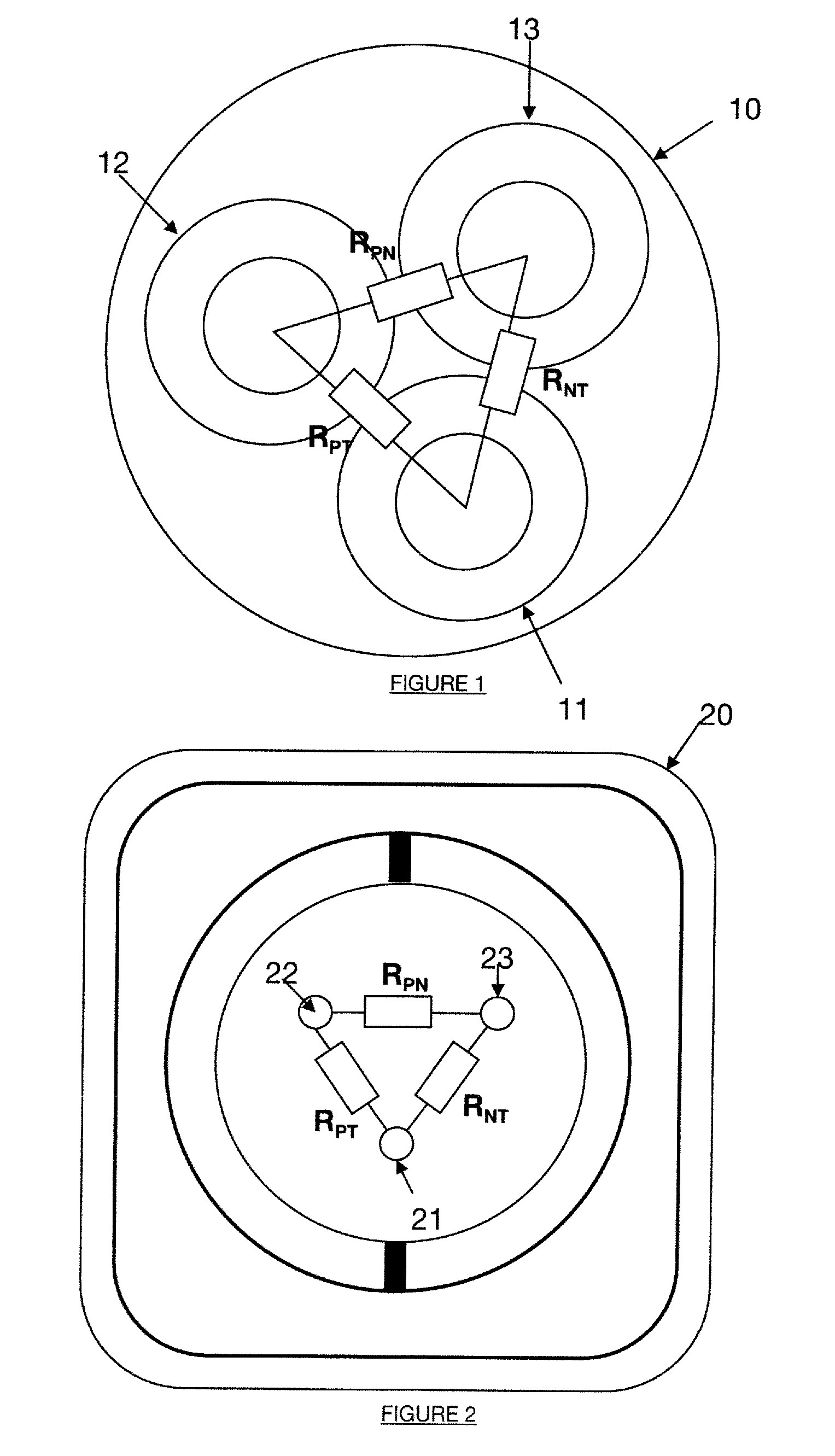
[0049]This matches the impedance of the socket outlets of the electrical installation concerned to prevent reflection of signals at the high-frequency PLT data transmission frequencies when they reach the socket. The impedance of a socket left open circuit or into which an electrical device is plugged is different from that of the electrical mains wiring. Reflection of the PLT signals is therefore to be avoided, and also reflection of high-frequency interference introduced into the installation by the electrical devices.
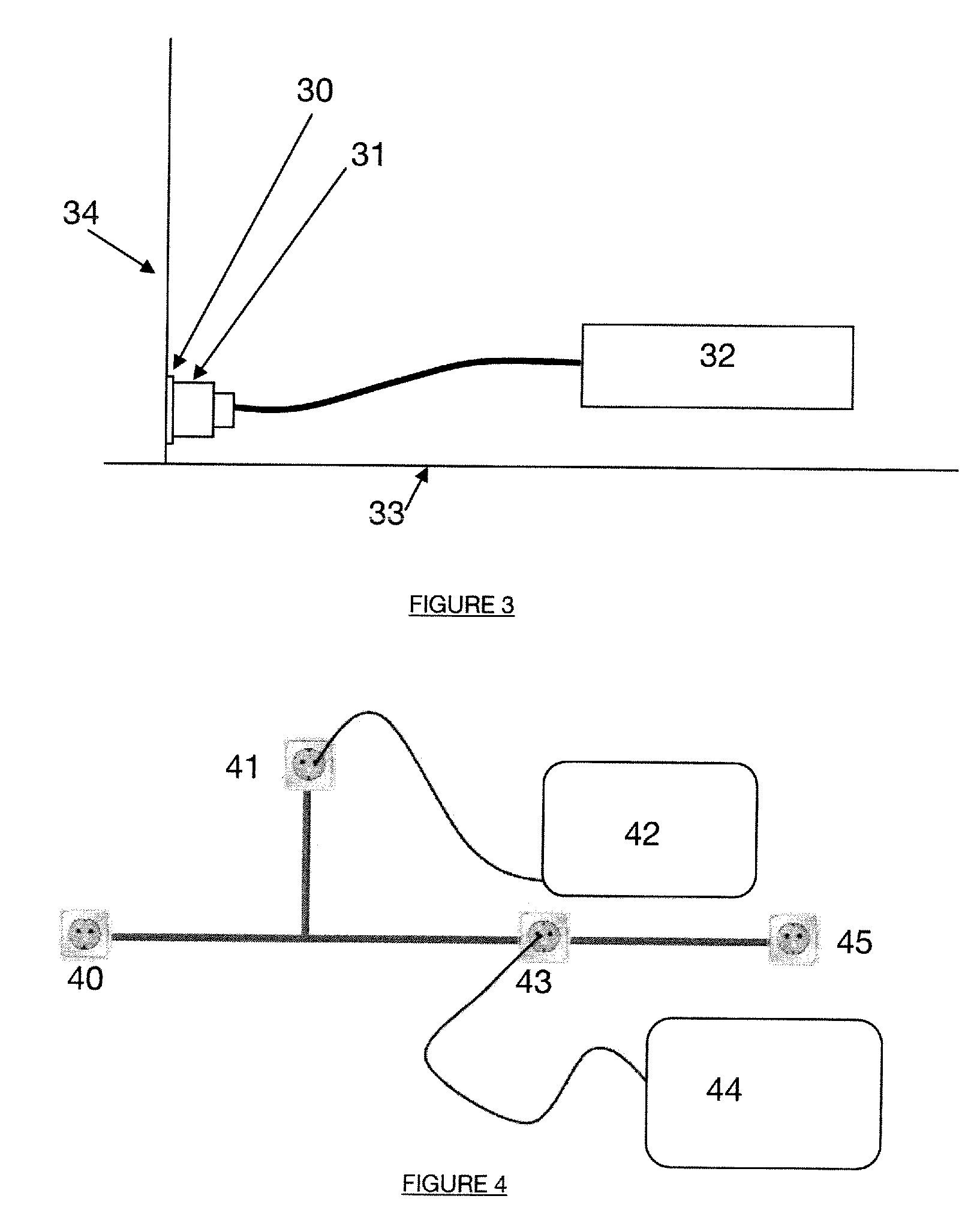
[0052]Thus the device according to an aspect of the disclosure is integrated directly into the electrical installation access sockets. Its presence is therefore transparent for the user of the installation. Furthermore, this prevents interference conducted by electrical devices plugged into the mains from entering the mains wiring. All or only some of the electrical socket outlets of the installation concerned incorporating a device of the present disclosure can be envisaged.
[0057]Installing the device in all socket outlets situated between the sender and the receiver of high bit rate signals minimizes the risk of introducing interference into the electrical mains wiring used to transmit the PLT signals. Equipping all the socket outlets of the electrical installation with the device, and not only those situated between two modems, can also be envisaged, of course.

Problems solved by technology

The electrical mains wiring of a domestic (or more generally “indoor”) installation constitutes a particularly difficult transmission medium for power line transmission.
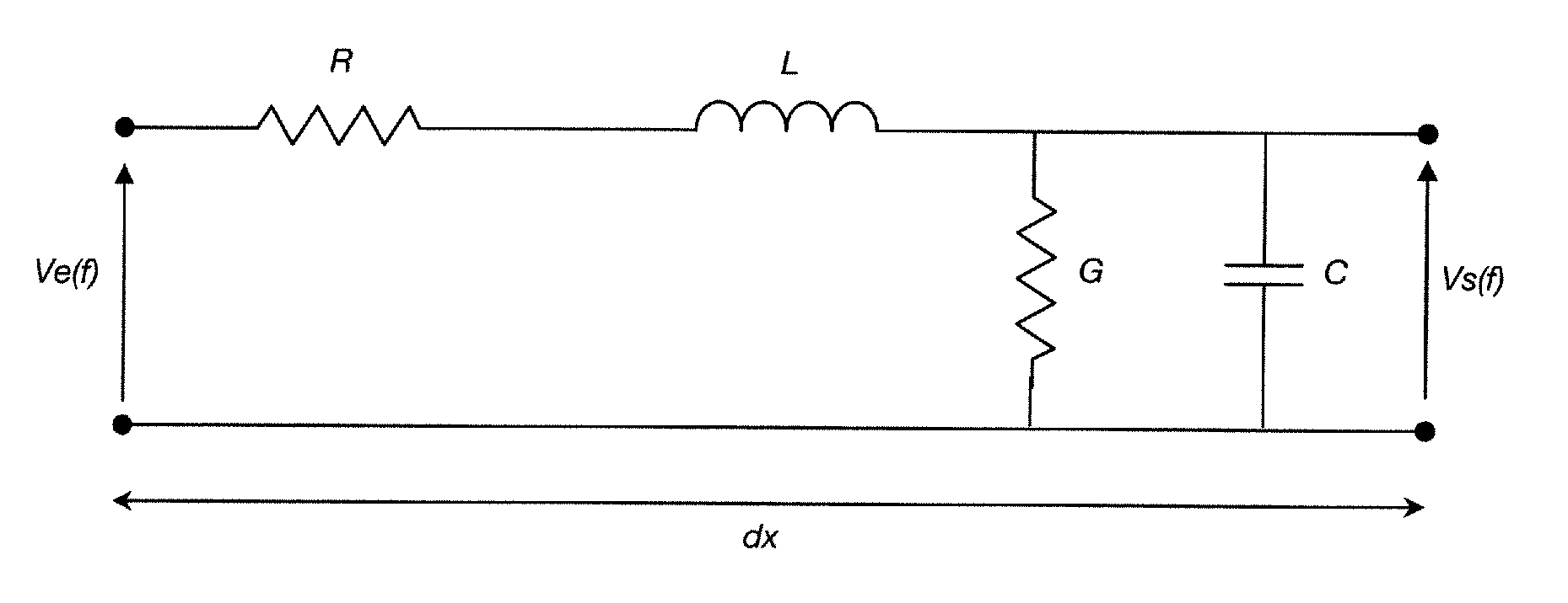
The inventors of this patent application have found that the transfer function of the transmission channel consisting of the electrical cable situated between two socket outlets of an electrical installation varies in a somewhat unpredictable manner.
As a consequence of these strong variations of the transfer function of the transmission channel, certain frequency bands are subject to severe fading, varying in time, which means that it is not possible to guarantee error-free transmission of signals at high bit rates.
However, that spectrum spreading technique has the drawback that it is effective only for transmission at low bit rates, and can therefore not be applied to power line transmission of signals at high bit rates.
However, that equalization technique has the drawback that it is particularly complicated.
A drawback of that technique is that it requires real-time evaluation of the transmission conditions on the electrical installation, in order to adapt the impedance of the device.
That kind of technique is corrective, and does not prevent the introduction of interference into the electrical installation.
Those methods all rely on digital processing of signals in the PLT modem and they therefore require software intervention at the modem level, which can be a problem with PLT modems already installed in an electrical installation, where updating the software may be difficult.

Method used


Image

  • Power line transmission
  • Power line transmission
  • Power line transmission

Examples


Embodiment Construction

[0068]The general principle of an aspect of the disclosure is based on using a physical device in a power line transmission system to adapt at least some network terminations (i.e. at least some socket outlets) to the characteristic impedance of domestic electrical mains wiring to prevent some kinds of interference entering the mains wiring.

[0069]One particular embodiment is described below in the context of a home equipped with a power line transmission system.

[0070]Signal attenuation is a recurrent problem in power line transmission systems, even though the distances concerned are short (at most a few hundred meters). This stems in particular from the large number of branch connections, i.e. secondary branches connected to the main path, ending at an open circuit or at devices that do not have an impedance matching that of the line.

[0071]The propagation channel is therefore subject to very high attenuation in homes including a large number of electrical socket outlets.

[0072]What i...


PUM


Abstract

A device including an element for receiving an electrical signal comprising a high-frequency data signal component and a low-frequency power supply component. The electrical signal is conveyed in an electrical cable of an electrical installation. The device further includes impedance matching operative in a band of frequencies of the high-frequency signal component, the impedance matching being determined as a function of one or more characteristics of the electrical cable. Such a device can be integrated into a socket outlet or an electrical device or take the form of a socket adaptor.

Description

CROSS-REFERENCE TO RELATED APPLICATIONS[0001]None.STATEMENT REGARDING FEDERALLY SPONSORED RESEARCH OR DEVELOPMENT[0002]None.THE NAMES OF PARTIES TO A JOINT RESEARCH AGREEMENT[0003]None.FIELD OF THE DISCLOSURE[0004]The field of the disclosure is that of power line transmission (PLT) of information.[0005]The disclosure applies in particular, although not exclusively, to transmission of multimedia (voice and / or data) information at high bit rates via the electrical mains wiring in a home (“indoor” application of PLT systems).BACKGROUND[0006]The power line transmission technique uses an electrical power distribution network as a communication infrastructure to transport digital information. It superimposes on the low-frequency electrical current (typically 50 hertz (Hz) in Europe or 60 Hz in the United States) a low-energy signal at a higher frequency. This high-frequency signal propagates along the lines of an electrical installation (for example the electrical mains wiring of a home)....

Claims


Application Information

Patent Timeline
IPC IPC(8): H03H7/38H02J3/02
CPCH04B3/56H03H7/427H03H7/06H04B2203/5466
Inventor ROBLOT, SANDRINEROBLOT, CHRISTOPHEZEDDAM, AHMED
Owner FRANCE TELECOM SA
Learn More