
All-solid-state cell

Inactive Publication Date: 2009-05-14
KYUSHU UNIV +1
View PDF13 Cites 48 Cited by
  • Summary
  • Abstract
  • Description
  • Claims
  • Application Information

AI Technical Summary

Benefits of technology

[0016]In view of the above problems, an object of the present invention is to provide such an all-solid-state cell that the particle boundary resistance of a solid electrolyte can be lowered in an electrode layer while preventing capacity reduction due to a reaction of the solid electrolyte with an electrode active material, a network of the solid electrolyte can be formed in the electrode layer, the connection interface area between the solid electrolyte and the electrode active material can be remarkably increased to lower the interface reaction resistance, and thus charge and discharge can be carried out even in the all solid state.
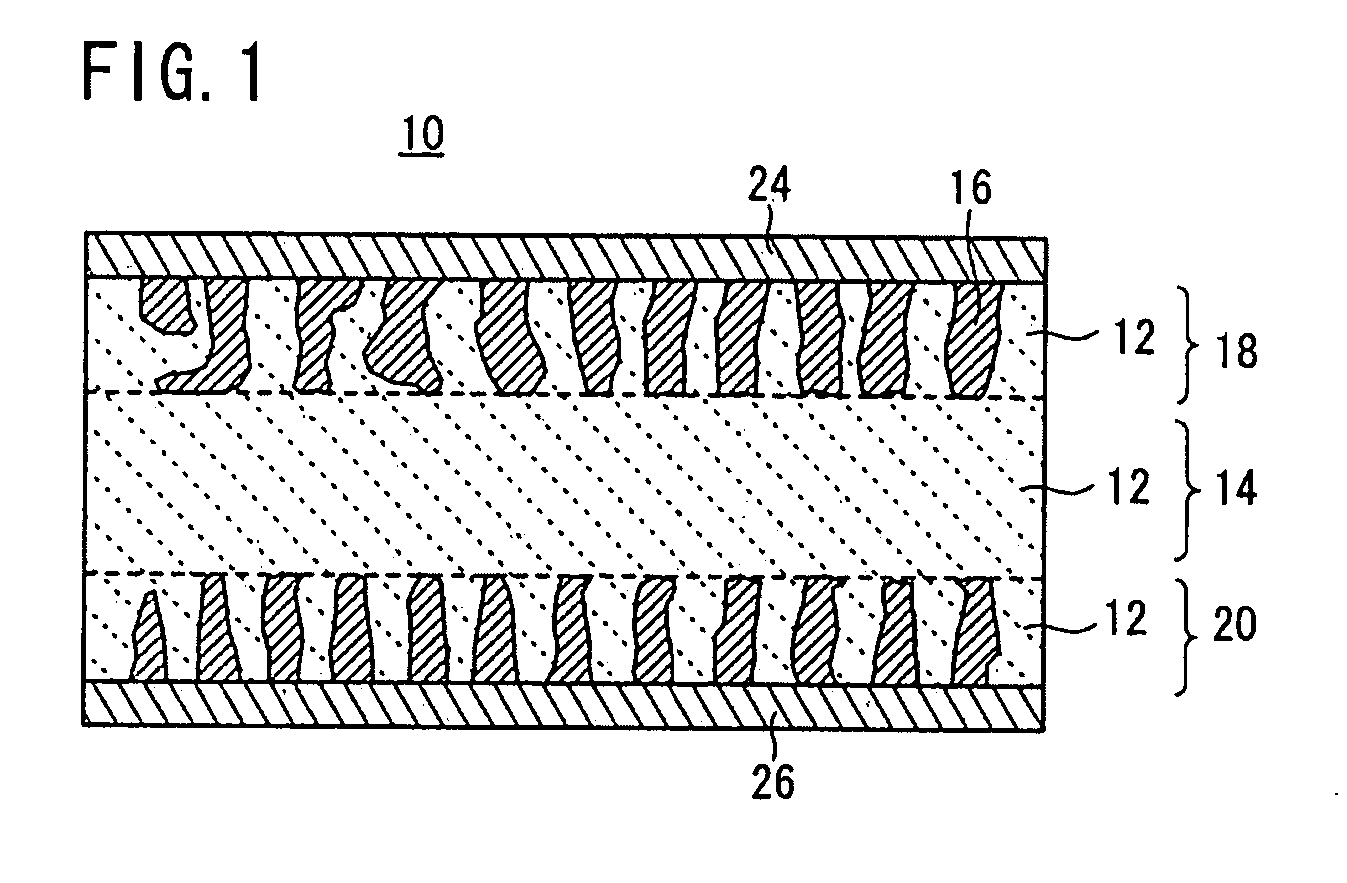
[0017]In research of an all-solid-state cell having an electrode layer composed of a mixture of a solid electrolyte material and an electrode active material, the inventors have found that the charge-discharge capacity of the electrode active material is reduced below its original theoretical capacity due to reduction in the crystallinity of the electrode active material and formation of a heterophase by a reaction between the solid electrolyte material and the electrode active material. Based on this finding, the inventors have further found that when a combination of the materials satisfies the inequality Ty>Tz (in which Ty is a temperature at which the capacity of the electrode active material is lowered by the reaction, and Tz is an initiation temperature at which the solid electrolyte material is shrunk by firing), an electrolyte network can be formed in the electrode layer to lower the resistance within the temperature range of Tz to Ty, the connection area between the materials can be increased while preventing the reaction between the electrolyte material and the electrode active material, and the interface reaction resistance at the connection interface between the materials can be lowered, whereby the resultant all-solid-state cell has a low internal resistance.

Problems solved by technology

The cell using such an electrolytic solution can cause problems of solution leakage, ignition, explosion, etc.
The electrodes of the cell have to be thin, and the amounts of the electrode active materials are limited.
Thus, the cell is disadvantageous in that it is difficult to achieve a high capacity.
However, an all-solid-state cell having positive and negative electrodes is not described in this report, and it is unclear whether the reaction resistance can be lowered in the electrolyte-electrode active material interface.
Furthermore, the electrolyte used in this report is a sulfide, which is expected to be unstable in the atmosphere (air).
The electrolyte may generate a toxic gas when brought into contact with the air due to breakage or the like.
Thus, this technology is disadvantageous in safety.
Therefore, the electrolyte can readily penetrate between particles of the electrode active material to form an electrolyte network in the electrode layers, resulting in a low interface reaction resistance.
As a result, the charge-discharge capacity of the active material was extremely reduced, and the active material was incapable of charge and discharge at its original theoretical capacity.
However, the solid electrolyte particles were not sufficiently sintered, the particle boundary resistance between the solid electrolyte particles was increased, and the connection interface area between the electrode active material and the solid electrolyte was not increased.
As a result, both the particle boundary resistance of the solid electrolyte and the interface reaction resistance of the electrode active material and the solid electrolyte could not be lowered, whereby the resultant all-solid-state cell had no charge-discharge capacity (no charge-discharge ability).

Method used


Image

  • All-solid-state cell
  • All-solid-state cell
  • All-solid-state cell

Examples


example 1

[0107]A binder was dissolved in an organic solvent, and an appropriate amount of the resultant solution was added to the LAGP glass powder and the LVP crystal powder. The mixture was kneaded in a mortar to prepare an electrode paste for screen printing. The obtained electrode paste was printed into an electrode pattern having a diameter of 12 mm on each surface of a fired solid electrolyte body (a base) having a diameter of 13 mm and a thickness of 1 mm. The printed electrode patterns were dried to form positive and negative electrodes.

[0108]The electrodes were bonded to the surfaces of the solid electrolyte base by firing at 600° C. for 2 hours using a firing furnace under an Ar atmosphere. Then, a sputtered gold (Au) film having a thickness of approximately 50 nm was formed as a collector on each surface of the resultant fired body.

[0109]After the firing, the positive electrode had a thickness of approximately 20 μm and an active material content of approximately 2 mg. The charge-...

example 2

[0110]A binder was dissolved in an organic solvent, and an appropriate amount of the resultant solution was added to the LAGP glass powder and the LVP crystal powder. The mixture was kneaded in a mortar to prepare an electrode paste for screen printing. The obtained electrode paste was printed into an electrode pattern and dried on each surface of a fired solid electrolyte body (a base) in the above-mentioned manner, to form positive and negative electrodes.

[0111]The electrodes were bonded to the surfaces of the solid electrolyte base by firing at 600° C. for 40 hours using a firing furnace under an Ar atmosphere. Then, a sputtered Au film was formed on each surface of the resultant fired body.

[0112]After the firing, the positive electrode had a thickness of approximately 20 μm and an active material content of approximately 2 mg as above.

example 3

[0124]An all-solid-state cell of Example 3 was produced, and the charge / discharge property and the alternating-current impedance property were measured.

[0125]In the same manner as Example 1, a binder was dissolved in an organic solvent, and an appropriate amount of the resultant solution was added to the LAGP glass powder and the LVP crystal powder. The mixture was kneaded in a mortar to prepare an electrode paste for screen printing. The obtained electrode paste was printed into an electrode pattern having a diameter of 12 mm on each surface of a fired solid electrolyte body (a base) having a diameter of 13 mm and a thickness of 1 mm. The printed electrode patterns were dried to form positive and negative electrodes.

[0126]The electrodes were bonded to the surfaces of the solid electrolyte base by firing while applying a load of 500 kg / cm2 in the thickness direction at 600° C. for 40 hours using a hot-press furnace under an Ar atmosphere. Then, a sputtered gold (Au) film having a th...


PUM


Abstract

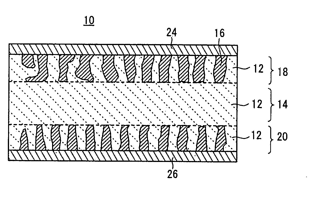
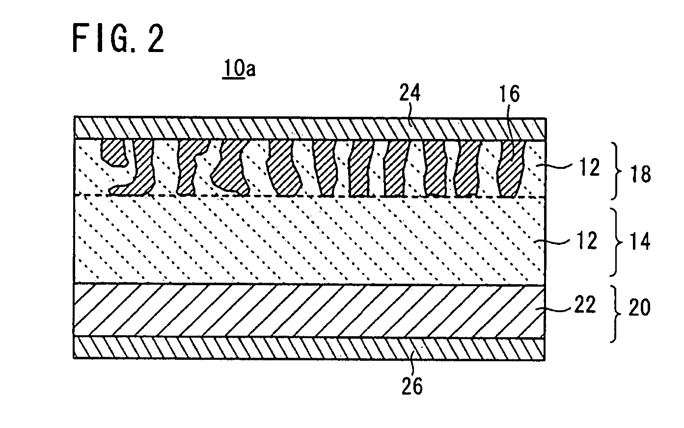
An all-solid-state cell has a fired solid electrolyte body, a first electrode layer integrally formed on one surface of the fired solid electrolyte body by mixing and firing an electrode active material and a solid electrolyte, and a second electrode layer integrally formed on the other surface of the fired solid electrolyte body by mixing and firing an electrode active material and a solid electrolyte. The first and the second electrode layers are formed by mixing and firing the electrode active material and the amorphous solid electrolyte, which satisfy the relation Ty>Tz (wherein Ty is a temperature at which the capacity of the electrode active material is lowered by reaction between the electrode active material and the solid electrolyte material, and Tz is a temperature at which the solid electrolyte material is shrunk by firing).

Description

CROSS-REFERENCE TO RELATED APPLICATIONS[0001]This application is based upon and claims the benefit of priority from Japanese Patent Application No. 2007-293682 filed on Nov. 12, 2007 and Japanese Patent Application No. 2008-268333 filed on Oct. 17, 2008 in the Japanese Patent Office, of which the contents are incorporated herein by reference.BACKGROUND OF THE INVENTION[0002]1. Field of the Invention[0003]The present invention relates to an all-solid-state cell utilizing a combination of an electrode active material and a solid electrolyte material.[0004]2. Description of the Related Art[0005]In recent years, with the advancement of portable devices such as personal computers and mobile phones, there has been rapidly increasing demand for batteries usable as a power source thereof. In cells of the batteries for the purposes, a liquid electrolyte (an electrolytic solution) containing a combustible organic diluent solvent has been used as an ion transfer medium. The cell using such an ...

Claims


Application Information

Patent Timeline
IPC IPC(8): H01M6/18H01M4/64H01M4/58H01M10/0562H01M10/36
CPCH01M4/5825H01M10/052H01M10/0562Y02E60/10
Inventor OKADA, SHIGETOKOBAYASHI, EIJIYAMAMOTO, KAZUHIROYOSHIDA, TOSHIHIROSATO, YOSUKE
Owner KYUSHU UNIV
Learn More