Eureka AIR delivers breakthrough ideas for toughest innovation challenges, trusted by R&D personnel around the world.

Foam skin insulation with support members

Inactive Publication Date: 2009-05-14
COMMSCOPE INC
View PDF11 Cites 3 Cited by
  • Summary
  • Abstract
  • Description
  • Claims
  • Application Information

AI Technical Summary

Benefits of technology

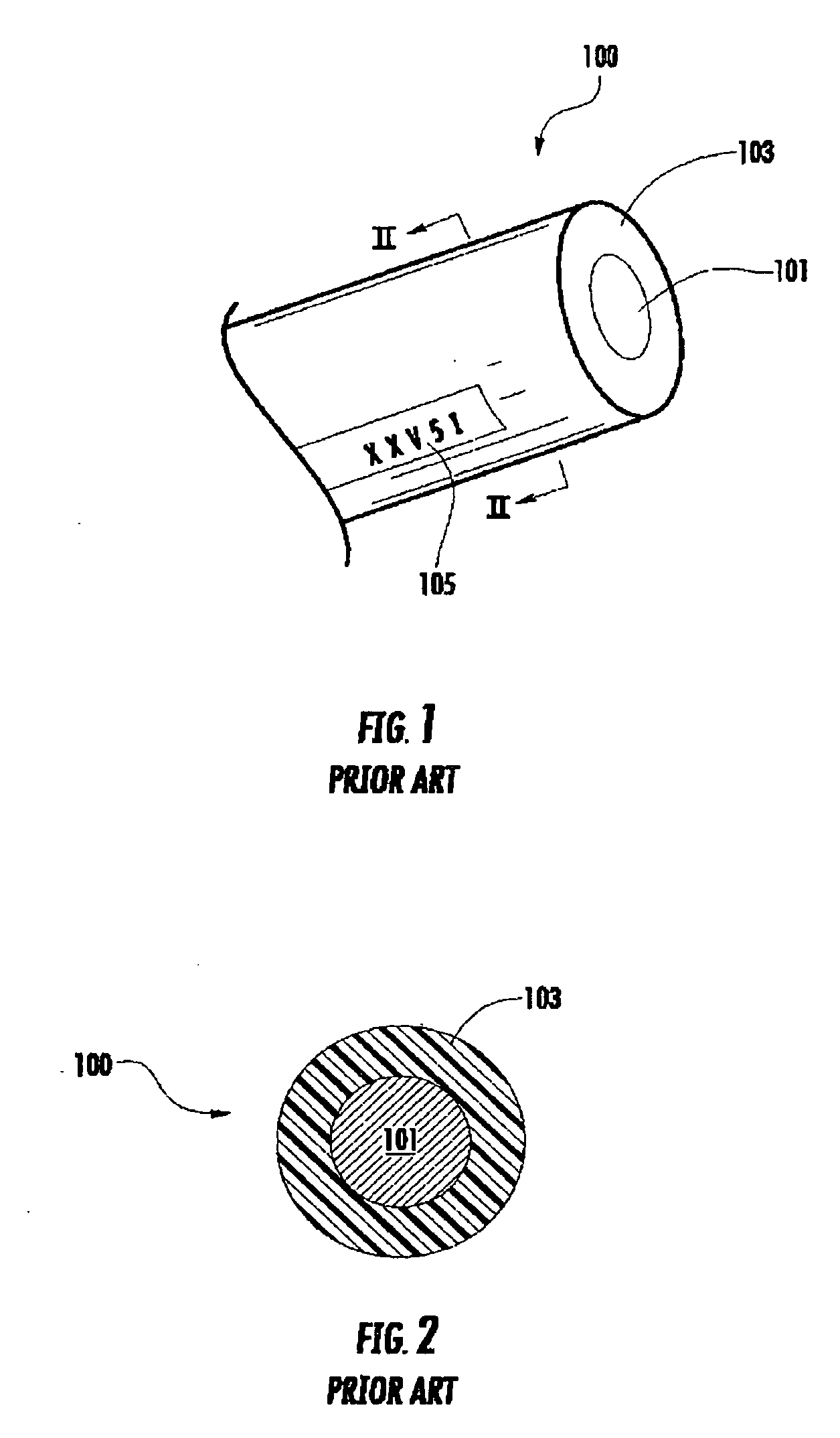
[0013]With the prior art embodiment of FIGS. 3-4, a foam insulation layer 113 surrounds and contacts the outer surface of the conductor 111. The foam insulation layer 113 has a relatively lower dielectric constant as compared to an outer protective layer 115. Therefore, the electrical performance of the wire 110 is enhanced relative to the wire 100. However, when the wire 110 is spooled prior to assembling a twisted pair cable, and when the wire 110 is twisted with another wire during the assembly of a twisted pair cable, the foam insulation layer 113 tends to compress, which may give the wire 110 an overall oval shape. This is accentuated by the tight twists found in Category 6 or 6A type cable designs. Compression of the foam insulation layer 113 changes the dielectric constant of the compressed portions adjacent to the outer surface of the conductor 111 by elimination of the closed-cell air pockets within those portions of the foam insulation layer 113. Hence, the electrical performance of the wire 110 may be degraded.
[0014]With the prior art embodiment of FIGS. 5-6, a series of air channels 125 (having a dielectric constant of about 1.0) and material forming the protective layer 123 (having a dielectric constant of generally greater than 2.0) surround the conductor 121. Therefore, an average value of the dielectric constant immediately adjacent to the outer surface of the conductor 121 can be reduced relative to the prior art wire 100 of FIG. 1-2, which improves the electrical performance of the wire 120. Applicant has appreciated that, during a typical manufacturing process of the wire 120, the extruded jacket material tends to expand and flow. With open air channels 125 adjacent to the projections 127, the hot tips of the projections 127 contacting the conductor 121 might tend to flow along the outer surface of the conductor 121 to form expanded tip portions. Therefore, the high dielectric material of the protective layer 123 can tend to be the material mostly in immediate contact with the outer surface of the conductor 121, where electrical signals primarily flow. Also, the projections 127 touch the outer surface of the conductor 121, which can create a series of areas with high dielectric constants (projections 127) and low dielectric constants (air channels 125) in contact with the outer surface of the conductor 121. As currents primarily flow on the outer surface of the conductor 121, this encountered variation in dielectric constant might be detrimental to the electrical performance of the wire 120. Also, the projections 127 can deform under compressive forces reducing the volume of the air pockets further increasing the dielectric constant of the insulation layer.
[0015]It is an object of the present invention to provide a wire with improved electrical performance, as compared to existing wires, and / or to address one or more of the drawbacks of the prior art wires 100, 110 and 120.
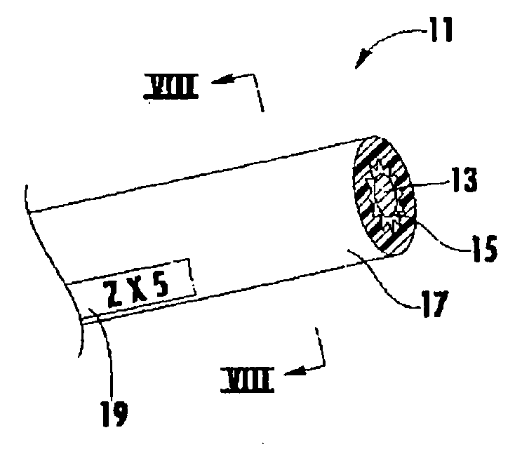
[0016]These and other objects are accomplished by a wire including a conductor. A foam insulation surrounds an outer surface of the conductor. A jacket surrounds the foam insulation and presents a plurality of projections on an inner surface thereof, which extend toward the conductor, yet do not purposefully contact the conductor. With the foam insulation having a lower dielectric constant than the jacket material, the electrical performance of the wire can be improved, while maintaining a good crush resistance.

Problems solved by technology

This can lead to drawbacks in that the electrical performance of the wire 100 is inferior.
In other words, a material with a high dielectric constant is directly contacting the outer surface of the conductor 101, where electrical signals travel, which can increase signal attenuation, leading to signal distortion and delay.
As currents primarily flow on the outer surface of the conductor 121, this encountered variation in dielectric constant might be detrimental to the electrical performance of the wire 120.

Method used


Image

  • Foam skin insulation with support members
  • Foam skin insulation with support members
  • Foam skin insulation with support members

Examples


Embodiment Construction

[0029]The present invention now is described more fully hereinafter with reference to the accompanying drawings, in which embodiments of the invention are shown. This invention may, however, be embodied in many different forms and should not be construed as limited to the embodiments set forth herein; rather, these embodiments are provided so that this disclosure will be thorough and complete, and will fully convey the scope of the invention to those skilled in the art.

[0030]Like numbers refer to like elements throughout. In the figures, the thickness of certain lines, layers, components, elements or features may be exaggerated for clarity. Broken lines illustrate optional features or operations unless specified otherwise.

[0031]The terminology used herein is for the purpose of describing particular embodiments only and is not intended to be limiting of the invention. Unless otherwise defined, all terms (including technical and scientific terms) used herein have the same meaning as c...


PUM

PropertyMeasurementUnit
Lengthaaaaaaaaaa
Fractionaaaaaaaaaa
Diameteraaaaaaaaaa

Abstract

A wire includes a conductor. A foam insulation surrounds an outer surface of the conductor. A jacket surrounds the foam insulation and presents a plurality of projections on an inner surface thereof, which extend toward the conductor, yet do not purposefully contact the conductor. With the foam insulation having a lower dielectric constant than the jacket material, the electrical performance of the wire is improved, while maintaining a good crush resistance.

Description

BACKGROUND OF THE INVENTION[0001]1. Field of the Invention[0002]The present invention relates to a wire. More particularly, the present invention relates to a wire with improved insulation for better performance in a twisted pair cable.[0003]2. Description of the Related Art[0004]As illustrated in FIGS. 1 and 2, a wire 100 for use with a twisted pair cable is well known in the industry. The typical wire 100 has a centrally located conductor 101 formed of solid or stranded copper. A protective layer 103 completely surrounds the conductor 101. The protective layer 103 is formed of a durable and nonconductive polymer and prevents the conductor 101 from making electrical contact with other conductive structures except at termination points (e.g. at an insulation displacement (IDC) connector).[0005]The protective outer layer 103 has been known to present drawbacks for the wire 100. First, the outer protective layer 103 must be formed of a relatively solid polymer in order to be durable (...

Claims


Application Information

Patent Timeline
IPC IPC(8): B23P15/00B23P19/04
CPCH01B7/0233Y10T29/49826Y10T29/49002H01B7/189
Inventor WESSELS, ROB
Owner COMMSCOPE INC
Why Eureka
Eureka Blog
Learn More