
Display with touch panel

a touch panel and display panel technology, applied in the field of flat panel display with a touch panel, can solve the problem that the display panel b>120/b> is still pressed by the impact force f, and achieve the effect of relieving the stress of the pressing for

Inactive Publication Date: 2009-05-07
CORETRONIC
View PDF2 Cites 17 Cited by
  • Summary
  • Abstract
  • Description
  • Claims
  • Application Information

AI Technical Summary

Benefits of technology

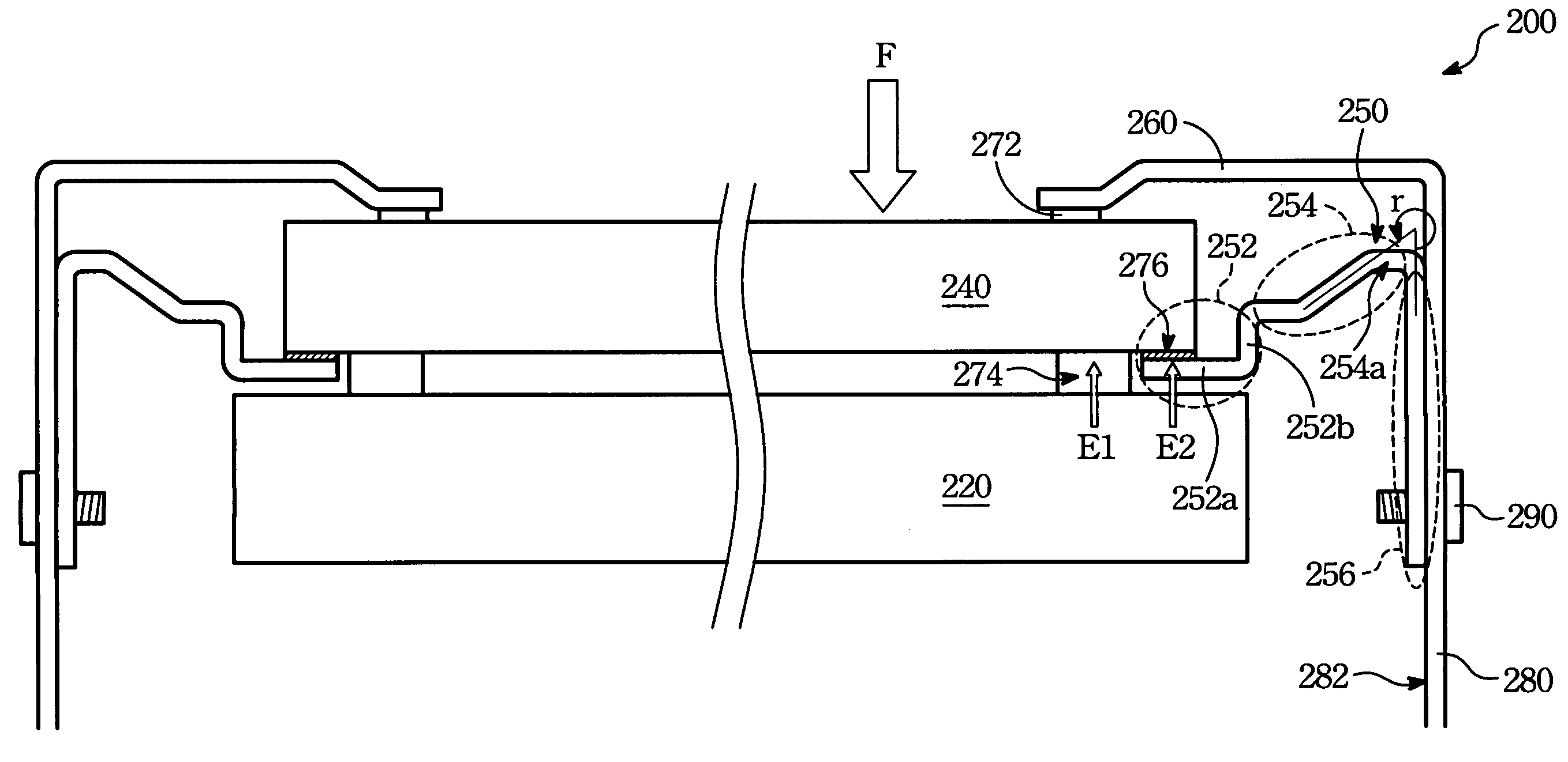
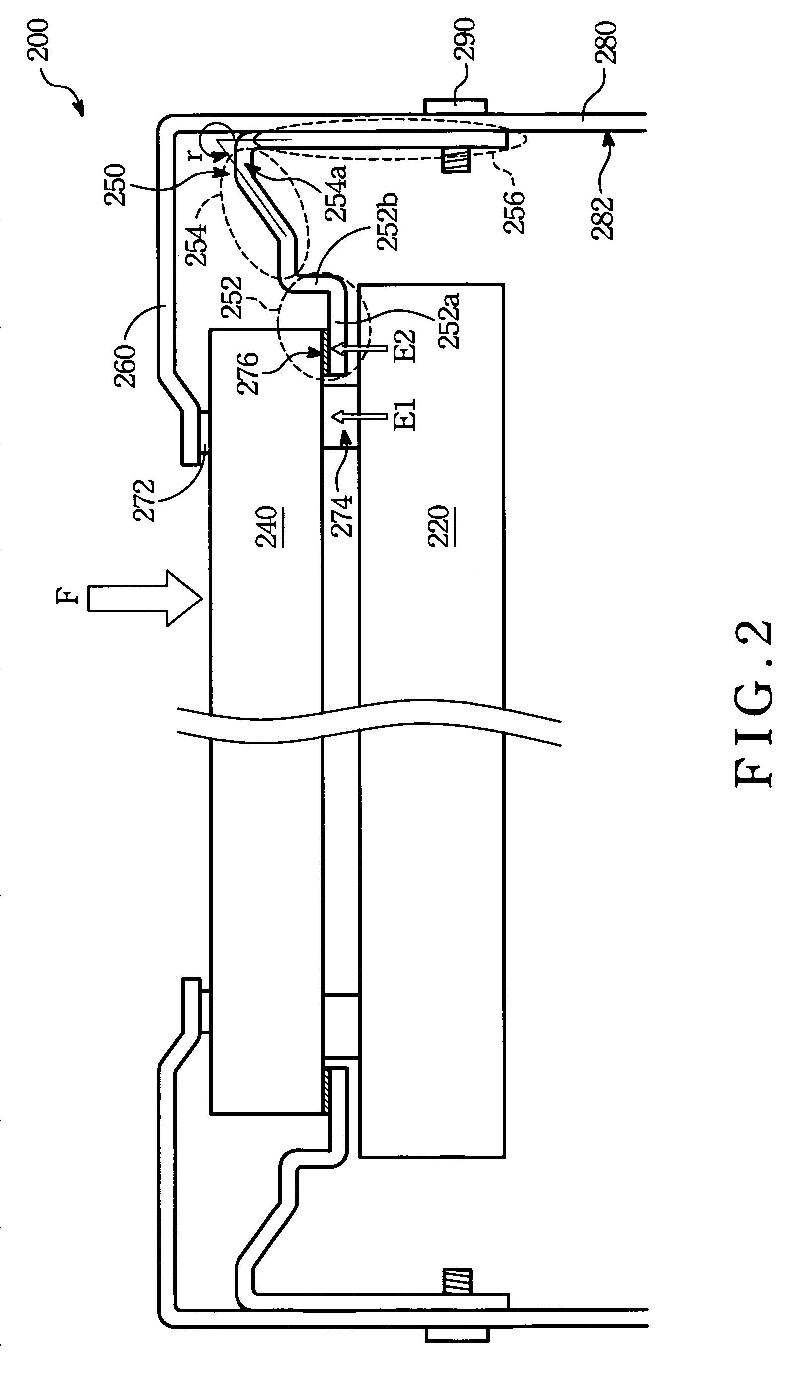
The present invention aims to prevent damage to the display panel of a flat panel display by reducing the pressing force from an impact force on the touch panel. The invention provides a supporting structure with an elastic unit that can bend with a changeable angle to absorb the impact force. The supporting structure also has a horizontal portion and a vertical portion that keeps a predetermined distance from the edge of the touch panel. Additionally, the invention includes a fixing unit and positioning pins for positioning the fixing unit on the sidewall of the back cover of the flat panel display. A side plate lining is also included to restrict the horizontal movement of the touch panel.

Problems solved by technology

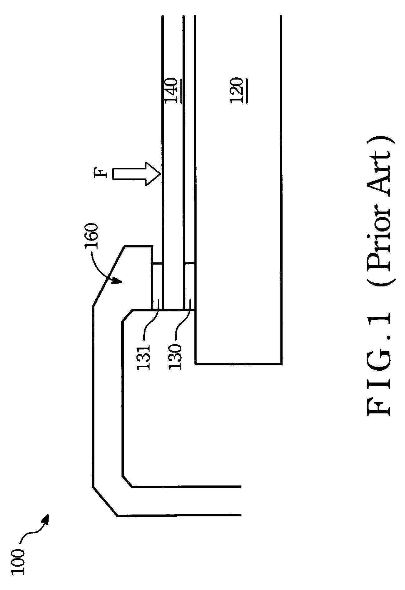
However, impact forces stressed to the touch panel may drive the touch panel pressing the display panel to result in damage.
However, even if the thickness of the touch panel 140 is increased, the problem that the display panel 120 is pressed by the impact force F is still existed.

Method used


Image

  • Display with touch panel
  • Display with touch panel
  • Display with touch panel

Examples


Embodiment Construction

[0023]In the following detailed description of the preferred embodiments, reference is made to the accompanying drawings which form a part hereof, and in which are shown by way of illustration specific embodiments in which the invention may be practiced. In this regard, directional terminology, such as “top,”“bottom,”“front,”“back,” etc., is used with reference to the orientation of the Figure(s) being described. The components of the present invention can be positioned in a number of different orientations. As such, the directional terminology is used for purposes of illustration and is in no way limiting. On the other hand, the drawings are only schematic and the sizes of components may be exaggerated for clarity. It is to be understood that other embodiments may be utilized and structural changes may be made without departing from the scope of the present invention. Also, it is to be understood that the phraseology and terminology used herein are for the purpose of description an...


PUM


Abstract

A flat panel display having a display panel, a touch panel, a supporting structure and a frame is provided. The touch panel is assembled on the display panel. The supporting structure has a supporting unit and an elastic unit at least. The supporting unit is utilized for carrying the touch panel. The elastic unit has a fixed end and an extending end. The extending end is connected to the supporting unit. The elastic unit has a bending with a changeable bending angle varied with the impact force stressed to the supporting unit. The frame is assembled on the touch panel to restrict vertical movement of the touch panel.

Description

BACKGROUND OF THE INVENTION[0001](1) Field of the Invention[0002]The present invention relates to a flat panel display with a touch panel, and more particularly relates to a flat panel display capable of preventing the display panel thereof being damaged by the impact force stressed on the touch panel.[0003](2) Description of the Prior Art[0004]In present, attending with the development of flat panel displaying technologies, flat panel displays have become a main stream product for the displaying industries. Meanwhile, many flat panel displays have integrated touch panels as an interface for users to input control signal by merely pressing the on-screen button.[0005]The touch panel is operated by being touched by the user. However, impact forces stressed to the touch panel may drive the touch panel pressing the display panel to result in damage. In order to prevent the display panel from being damaged by the touch panel, proper supporting units are demanded to carry the touch panel....

Claims


Application Information

Patent Timeline
Patent Type & Authority Applications(United States)
IPC IPC(8): G06F3/041G06F3/033G06F3/0354
CPCG02F1/133308G02F1/13338G06F3/041G06F3/03547G02F2001/13332G06F1/1601G02F1/13332
Inventor CHUEH, CHIEN-TSAI
Owner CORETRONIC
Learn More