Process for Producing a Substantially Shell-Shaped Component

a technology of substantially shell-shaped components and shells, which is applied in the direction of transportation and packaging, other domestic articles, efficient propulsion technologies, etc., can solve the problems of frequent integration, no longer having the desired contour on the outer side, and possible double-run over with considerable outlay, etc., to achieve low cost, reduce production costs, and facilitate production

Active Publication Date: 2009-05-07
AIRBUS OPERATIONS GMBH
View PDF8 Cites 4 Cited by
  • Summary
  • Abstract
  • Description
  • Claims
  • Application Information

AI Technical Summary

Benefits of technology

[0019]The doubler is manufactured separately, with the result that the process of laying the shell skin is not slowed down by small thickened portions.
[0021]The separately manufactured doubler can be prefabricated using virtually any desired combinations of materials and laminate structures and can be separately machined and tested prior to installation. This allows the manufacturing risk involved in the overall shell-shaped component to be reduced in particular in the case of large wall thicknesses.
[0023]The stiffening elements can in principle be of any suitable shape. In one particular embodiment, the stiffening elements are formed using reinforcing profiled sections, in particular T-profiled sections, double T-profiled sections, L-profiled sections, Z-profiled sections, rectangular profiled sections or the like, so that the stability is particularly high and the reinforcing elements can be manufactured at low cost by extrusion etc. as material made by the meter, with the extrudates being cut to length as required.

Problems solved by technology

However, in terms of technical implementation, it is only possible to run over a doubler with considerable outlay.
Although the stiffening elements can generally be produced with a moderate offset, integration represents a frequent cause of complications during manufacture.
However, the outer side no longer has the desired contour, which has an adverse effect on aerodynamics for example in the case of aircraft structures.
Furthermore, the use of external doublers involves a number of manufacturing drawbacks.

Method used


Image

  • Process for Producing a Substantially Shell-Shaped Component
  • Process for Producing a Substantially Shell-Shaped Component

Examples


Embodiment Construction

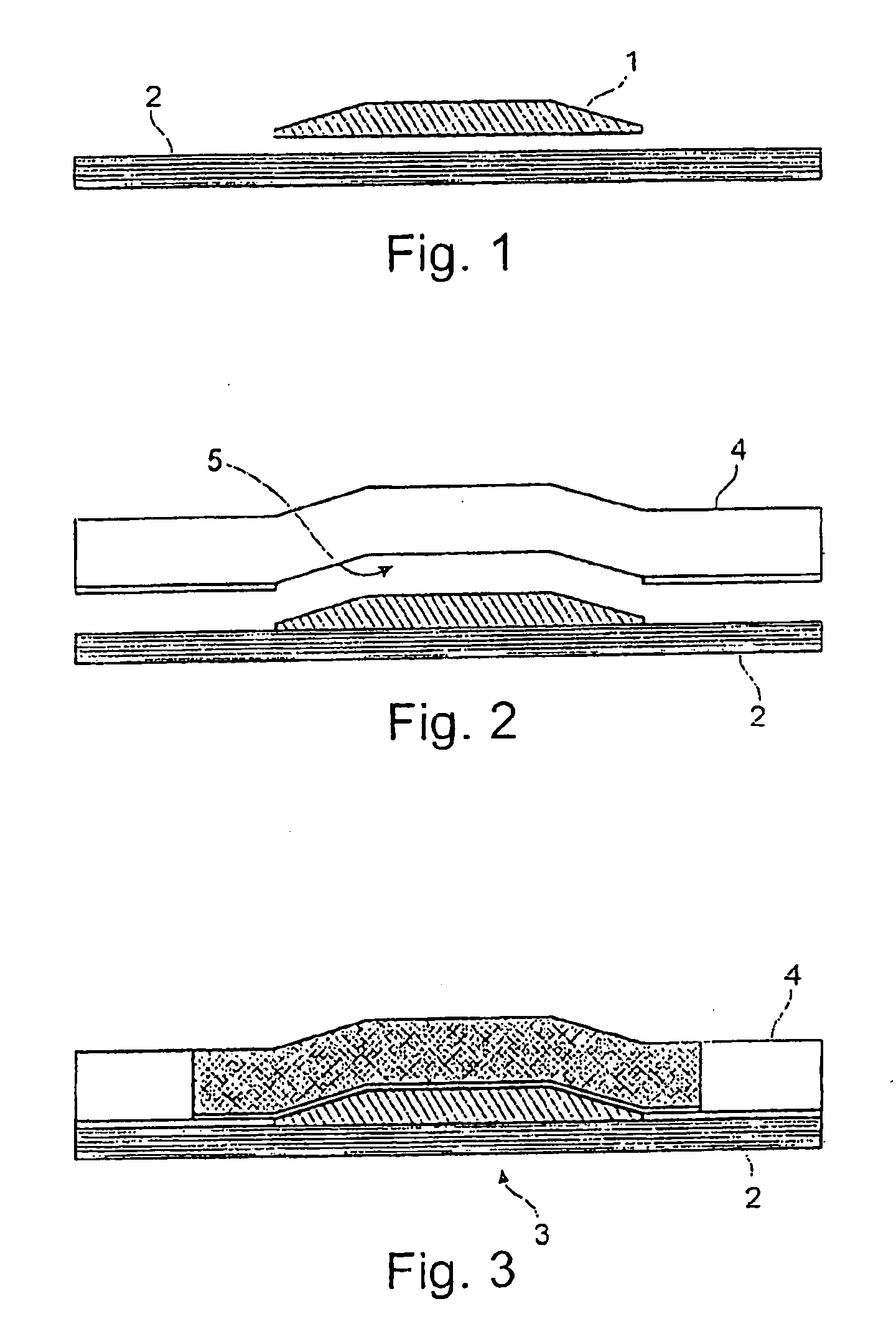
[0031]Reference is made to FIG. 1 to 3.

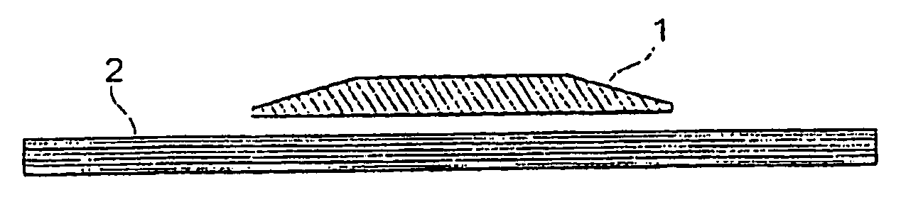
[0032]The figures illustrate the production of a shell-shaped component which is provided with a stiffening element formed as a stringer 4, wherein a thickening configured as a doubler 1 is formed in a reinforcing zone 3 to improve the introduction of load. In this case, semi-finished products, known as prepreg material, are used. The prepreg material is a carbon-fiber-reinforced sheet-like structure impregnated with a curable epoxy resin. Alternatively, it is also possible to use curable polyester or BMI resin systems for prepreg materials.

[0033]First of all, the shell skin 2 is laid in an uncured state, for example using the known “ATL” (“automated tape laying”) process. The ATL process is a process for the automated production of laminates, in which unidirectional laid fiber fabrics, for example comprising carbon fibers or the like, are laid.

[0034]The cured and finish-machined doubler 1 is positioned on the uncured shell skin 3 at the locati...


PUM

PropertyMeasurementUnit
pressureaaaaaaaaaa
temperatureaaaaaaaaaa
pressureaaaaaaaaaa

Abstract

Disclosed is a process for producing a substantially shell-shaped component, from substantially carbon-fiber-reinforced synthetic material having at least one local reinforcing zone and at least one stiffening element, in particular a fuselage shell, a wing shell, a vertical stabilizer shell or horizontal stabilizer shell of an aircraft or the like. The process according to the invention comprises the following steps:arranging at least one doubler which has already been cured, on an at most partially cured shell skin to form the local reinforcing zone,applying at least one stiffening element which has already been cured, andplacing at least one at most partially cured connecting angle bracket against the at least one stiffening element at least in the region of the at least one doubler, andcuring the shell skin and the connecting angle bracket.

Description

FIELD OF THE INVENTION[0001]The invention relates to a process for producing a substantially shell-shaped component substantially from carbon-fiber-reinforced synthetic material, having at least one local reinforcing zone and at least one stiffening element. In particular, the invention relates to a process for producing a fuselage shell, a wing shell, a vertical or horizontal stabilizer shell of an aircraft or the like.[0002]However, the invention can in principle be used to produce components of any desired shape in a fiber composite structure, which have at least one reinforcing element and require at least one local reinforcing zone for local load introduction regions.BACKGROUND OF THE INVENTION[0003]It is known for shell-shaped components that have been stiffened by stiffening elements to be partially provided with local thickened portions (referred to below as doublers), in order to absorb high load concentrations in individual portions of the component structure and to distri...

Claims


Application Information

Patent Timeline
Patent Type & Authority Applications(United States)
IPC IPC(8): B64C1/00B29C35/00B29C48/76B29D99/00
CPCB29C70/44B29C70/84Y02T50/433B29L2031/3085B64C1/12B29L2031/3082Y02T50/40
Inventor LAW, BARNABYSCHUMACHER, KAIKOMADINA, JONATHONMUELLER, JOCHENHELTSCH, NORBERT
Owner AIRBUS OPERATIONS GMBH
Why Eureka
Try Eureka