[0016]As previously described, a sensor control device capable of increasing the detection precision of the specific gas component by the gas sensor may be employed in a gas sensor handling very small current signals. This sensor may be, for instance, an NOx sensor which generates a first
concentration response signal as one of
concentration response signals. The first concentration response signal reflects current flowing through the second oxygen pump cell in response to NOx concentration, as described in the third aspect. If the correcting
process operation is carried out in consideration of the effect of the circuit board temperature on the electronic components, then the detection precision of the NOx concentration can be improved. In particular, in an NOx sensor containing a detecting element including a first oxygen pump cell and a second oxygen pump cell, the current flowing through the second oxygen pump cell has a magnitude on the order of μA. Consequently, if the correcting
process operation is carried out in consideration of the effect of temperature, then very advantageous effects can be achieved.
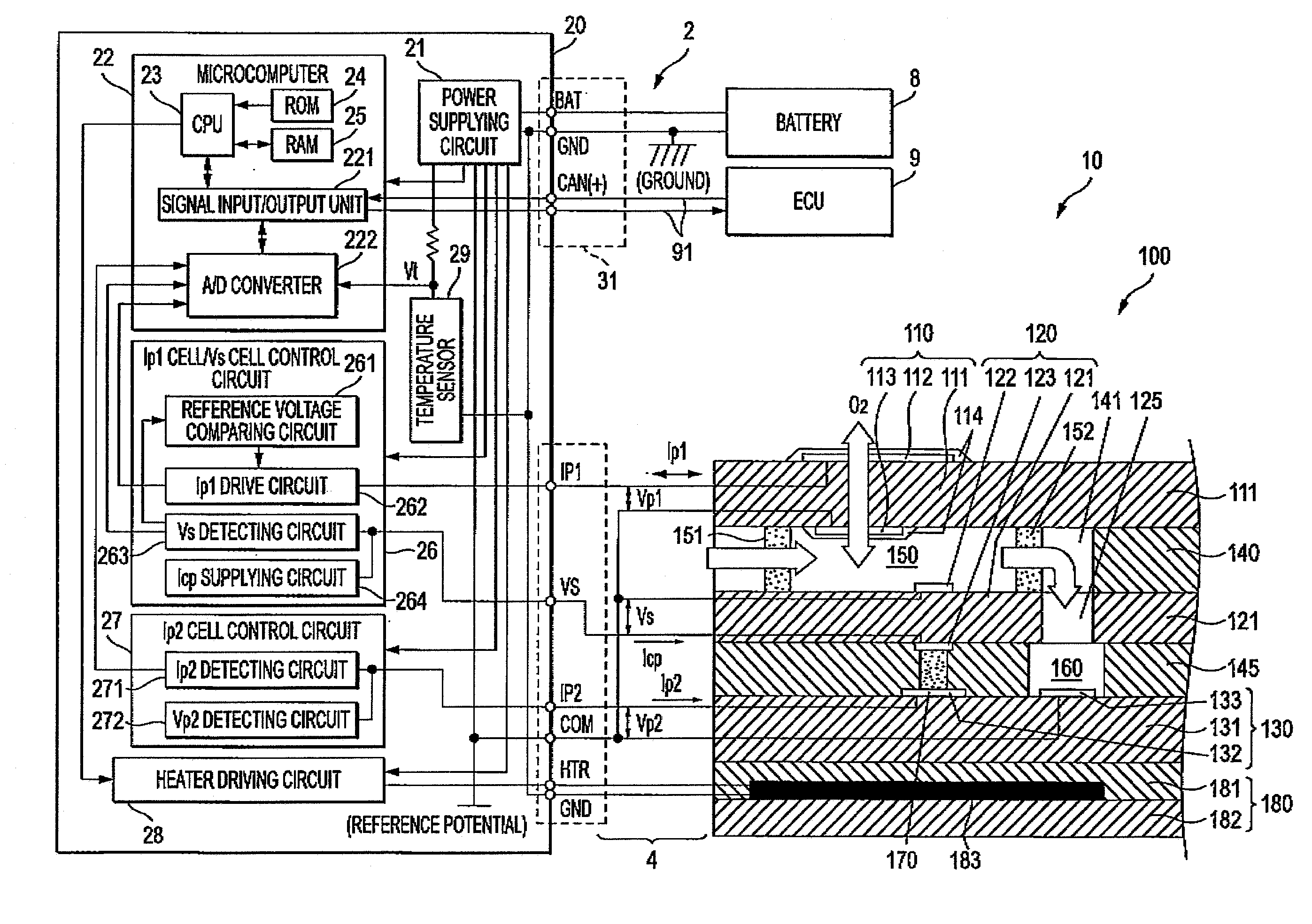
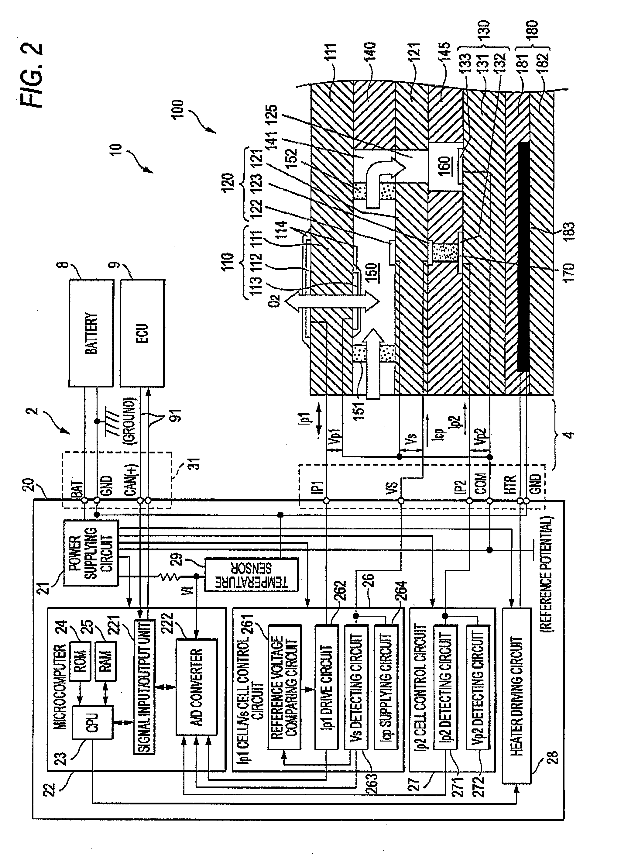
[0017]In such an NOx sensor, a heater element for heating the detecting element may be provided. Thus, a heater element driving unit for energizing the heater element may be mounted on the circuit board on which the detecting element driving unit is mounted. However, since a relatively large current is supplied to heat the
heating element, the electronic components provided on the circuit board in the heater element driving unit may generate a relatively large amount of heat. Also, in the NOx sensor including a first oxygen pump cell and a second oxygen pump cell, the current flowing through the second oxygen pump cell has a magnitude on the order of μA, which current is smaller than the current (normally, on the order of mA) flowing through the first oxygen pump cell. As a result, when the first
cell control circuit is compared with the second
cell control circuit, the current flowing through the energizing circuit of the second
cell control circuit is easily influenced by a variation in the temperature of the circuit board.
[0018]As a consequence, in the fourth aspect, in the case where the first and second cell control circuits constituting the detecting element driving unit are arranged on the circuit board, the second cell
control circuit is located farther from the heater element driving unit than the first cell
control circuit, and the
temperature sensing element is located closer to the arranging position of the detecting element driving unit than the arranging position of the heater element driving unit, or the
temperature sensing element is arranged within the detecting element driving unit. Since the second cell
control circuit is located farther from the heater element driving unit than the first cell control circuit, the heat generated by the heater element driving unit hardly affects the second cell control circuit, so that temperature variations of the circuit board can be suppressed to a relatively small degree in the second cell control circuit. As a result, it is possible to reduce the adverse influence due to temperature variation of the circuit board, which is superimposed on the first concentration response signal. In addition, in accordance with the fourth aspect, the temperature sensing element is located closer to the detecting element driving unit than the heater element driving unit, or the temperature sensing element is arranged within the detecting element driving unit. Accordingly, the temperature of the circuit board, to which the electronic components constituting the detecting element driving unit is subjected, is correctly detected. Consequently, it is possible to further improve precision in correcting errors due to temperature variation of the circuit board with respect to the first concentration response signal.
[0019]According to the fifth aspect, the NOx sensor comprising a detecting element including the first oxygen pump cell and the second oxygen pump cell may also include a second concentration response signal subject to temperature-correction, where the second concentration response signal represents a very small current which flows through the first oxygen pump in response to the oxygen concentration. Therefore, the detection precision of the oxygen concentration can be improved by performing the correcting
process operation (in consideration of the adverse influence due to the temperature of the circuit board affecting the electronic components) with respect to the second concentration response signal.
[0020]The adverse influence of heat, to which the electronic components mounted on the circuit board are subjected, is greatly affected by the
heat transfer (conduction) in the circuit board relative to the
radiation heat radiated from other electronic components through the air. In the sixth aspect, the temperature sensing element contacts the circuit board so as to detect the temperature of the circuit board. Accordingly, an error in the
gas concentration information, due to the adverse influence imparted by the temperature of the circuit board to which the electronic components are subjected, can be precisely corrected. As a result, the concentration of a specific gas component can be detected with higher precision.
