Eureka AIR delivers breakthrough ideas for toughest innovation challenges, trusted by R&D personnel around the world.

Automatic antenna tuner system for RFID

a technology of automatic antenna tuner and rfid, which is applied in the direction of mechanical actuation of burglar alarms, instruments, pulse techniques, etc., can solve the problems of low maintenance, severe impact on the efficiency of the antenna, and easy environmental impact on the remote power generating loop antenna in the facility, so as to improve the q or quality of the loop, the effect of reducing the resistance of the coil

Inactive Publication Date: 2009-04-30
COOPER TIRE & RUBBER COMPANY
View PDF27 Cites 16 Cited by
  • Summary
  • Abstract
  • Description
  • Claims
  • Application Information

AI Technical Summary

Benefits of technology

[0005]The antenna tuner of the present invention can power up a passive tag out to four feet in a field of 30 by 60 feet and can be used to wake up an active transponder tag that uses no battery current until awakened, thereby increasing its life over the expected life had it been in the continually awakened state.
[0008]The need to re-tune the loop antenna is important in order to maximize the generation of power at all times. As equipment is relocated in the facility and the power generation antenna becomes detuned, the efficiency is reduced. A worker will have to manually go out to the factory from time to time to optimize the loop antenna's tuning.
[0010]The automatic antenna tuner of the present invention is designed to test the resonance of the loop antenna at predetermined intervals to maintain the integrity of the loop antenna. Then when the computer system that is doing an inquiry of the area needs to power up the electronic devices positioned throughout the facility, the loop antenna will work efficiently as designed to power up such RFID transponder tags or other electronic devices.
[0012]One preferred embodiment of the present invention is to increase the capability over current battery technology by maintaining an ongoing charge to power remotely positioned electronic devices, thereby providing a potentially infinite shelf life for such devices. This will have significant advantages in reliability of the utilizing equipment. The present invention could also provide an external power source for medical, biomedical, night vision, GPS, radios, sensors, actuators and intelligence gather technologies.

Problems solved by technology

These electronic devices are typically without batteries and therefore require minimal or no maintenance.
This means that the tuning is critical and must be maintained at all times. A remote power generating loop antenna in a facility can easily be affected by the environment that it is in.
The efficiency of the antenna can be severely affected to a point where it is no longer tuned to the peak and therefore not able to perform its required function.

Method used


Image

  • Automatic antenna tuner system for RFID
  • Automatic antenna tuner system for RFID
  • Automatic antenna tuner system for RFID

Examples


Embodiment Construction

)

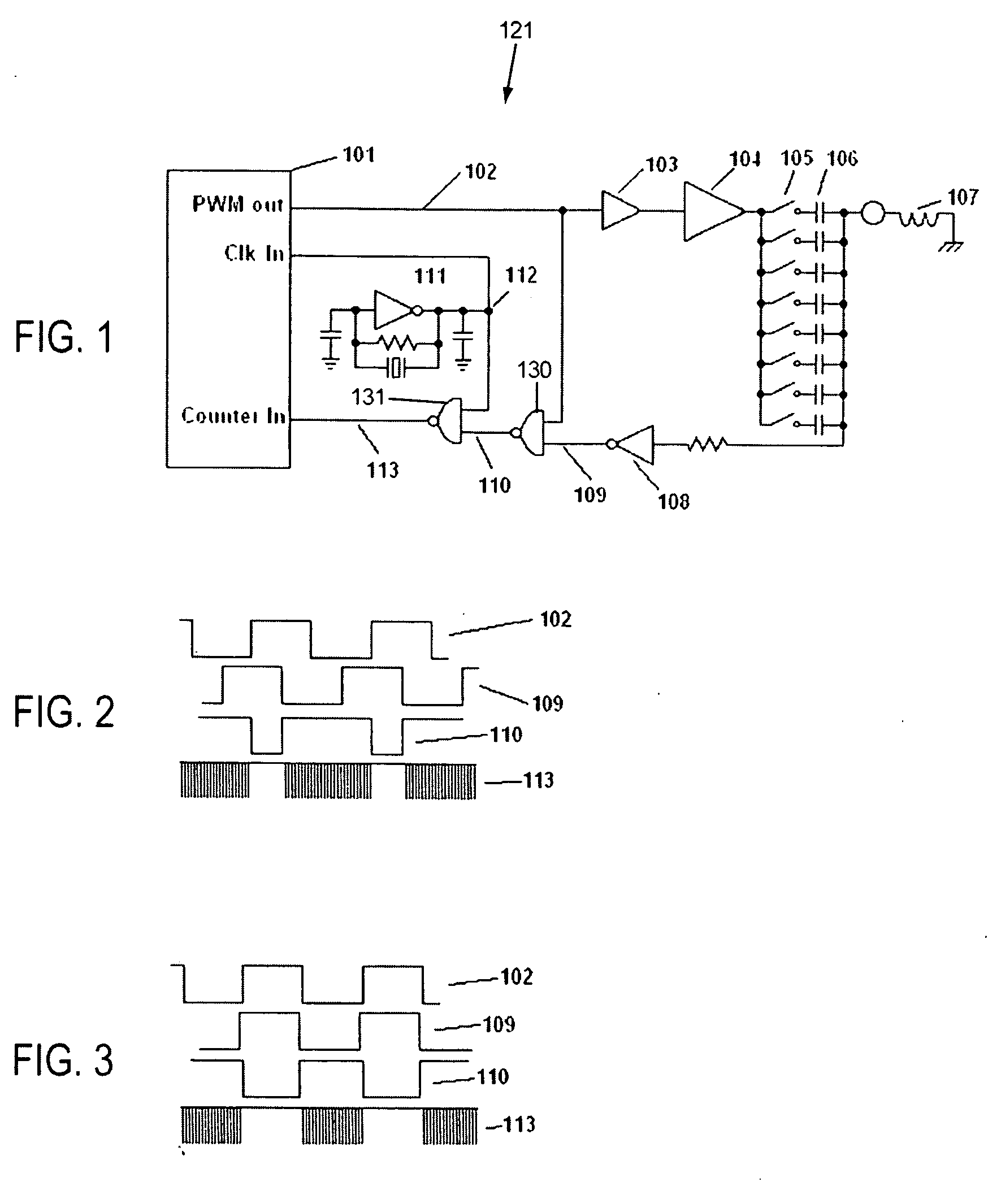
[0022]FIG. 1 illustrates the schematic of the basic circuit for the automatic antenna tuner system 121 of the present invention. A microprocessor 101 similar to Microchip Inc.'s PIC16F628 controls the generation of the frequency of a source signal 102 out of a pulse width modulation (PWM) output pin. This source signal 102 is 125 kHz for this design but can be almost any frequency desired to power up the wireless peripherals in its electromagnetic field. The source signal 102 is amplified by a MOSFET driver 103 and then driven into a pair of heavy MOSFET transistors 104. For example, the MOSFET driver 103 could be one manufactured by Microchip as its Model No. TC4422 which amplifies the power up to a level that the high capacitance inputs of the MOSFETs 104 require. These MOSFETs are designed to drive heavy currents and high voltage to drive a bank of capacitors 106. The MOSFET 104 could be one manufactured by International Rectifier as its Model No. JRF9530 and IRF530. These capac...


PUM


Abstract

An automatic antenna tuner system for radio frequency identification system includes a pulse width modulator, a microprocessor for controlling the generation of a source signal from the modulator, capacitors for receiving the source signal from amplifiers and transmitting it to an inductor, a gate communicating with the capacitors for transmitting a resonating signal from the inductor and capacitors as a carrier signal and means for gating the carrier signal with the source signal to produce a compared signal to produce a string of pulses and means for varying capacitance to increase or decrease the count of the string of pulses.

Description

CROSS REFERENCE TO RELATED APPLICATION[0001]This application is based upon and claims the benefit of U.S. Provisional Application No. 60 / 994,834 filed Sep. 24, 2007.BACKGROUND OF THE INVENTION[0002]In the manufacture and use of RFID (Radio Frequency Identification), the technology is divided into two major groups; The first group is Passive Tags that gather their power from close coupling to a reader, thus enabling them to transmit or reflect information back to the reader. The second groups is Active Tags, which have their own power storage capability like a battery, capacitor or other devices. The active tag is queried with an RF signal generated by the reader requesting the tag to transmit the data, which data is received by the reader. Passive tags typically have a range of a few inches up to a meter. Active tags can transmit tens of meters but have a limited life due to the battery limits. The active tag has a limited life due to the battery or capacitor's limited shelf life.[0...

Claims


Application Information

Patent Timeline
IPC IPC(8): H03K7/08H04B7/00
CPCH03J2200/10H03H7/40H01Q1/2208H01Q7/005
Inventor TUCKER, RANDALL L.CARROLL, GARY T.CARROLL, JOHN T.
Owner COOPER TIRE & RUBBER COMPANY
Why Eureka
Eureka Blog
Learn More