
Radiation treatment system with a beam control magnet

a technology of beam control and treatment system, which is applied in the direction of beam deviation/focusing by electric/magnetic means, instruments, mass spectrometers, etc., can solve the problem of increasing the weight of the rotatable gantry, and achieve the effect of improving the focusing properties

Inactive Publication Date: 2009-04-09
SIEMENS AG
View PDF2 Cites 7 Cited by
  • Summary
  • Abstract
  • Description
  • Claims
  • Application Information

AI Technical Summary

Benefits of technology

[0012]The present embodiments may obviate one or more of the drawbacks or limitations inherent in the related art. For example, in one embodiment, a radiation treatment system is flexible with regard to the positionability of the scanner magnets. In another example, a control beam has improved focusing properties.
[0017]Compared to location of the primary and secondary coils in the first region, in the second region the primary coils and the secondary coils can be displaced in the first direction, into a position with a greater radius R. In the second region, the additional coil, compared to the location of the additional coil in the first region, can be displaced in the second direction, into a position with a smaller radius. The system includes an especially simple and effectively designed beam control magnet.
[0021]The XY scanner magnet can be an X scanner magnet or a Y scanner magnet that is rotatable about the axis of the particle path. One of the two scanner magnets can be dispensed with using the XY scanner magnet. Accordingly, the space and cost for the radiation treatment system is reduced.
[0022]The conductors of the individual coils of the beam control magnet of the radiation treatment system can be made from superconductor material, such as from LTC superconductor material or HTC superconductor material. A radiation treatment system with superconducting deflection magnets is lighter in weight and smaller than a radiation treatment system with conventionally embodied electromagnets. Because the radiation treatment system can be reduced in its size, there is a considerable cost advantage for such a radiation treatment system. LTC superconductor material is technologically easily mastered and can be suitably processed. HTC superconductor material is advantageous, since the effort and complexity for cooling for maintaining the superconduction is less.

Problems solved by technology

Scanner magnets moreover occupy considerable space in the gantry of a pig and furthermore increase the weight of the rotatable gantry.

Method used


Image

  • Radiation treatment system with a beam control magnet
  • Radiation treatment system with a beam control magnet
  • Radiation treatment system with a beam control magnet

Examples


Embodiment Construction

[0030]Components corresponding to one another in the drawings are identified by the same reference numerals.

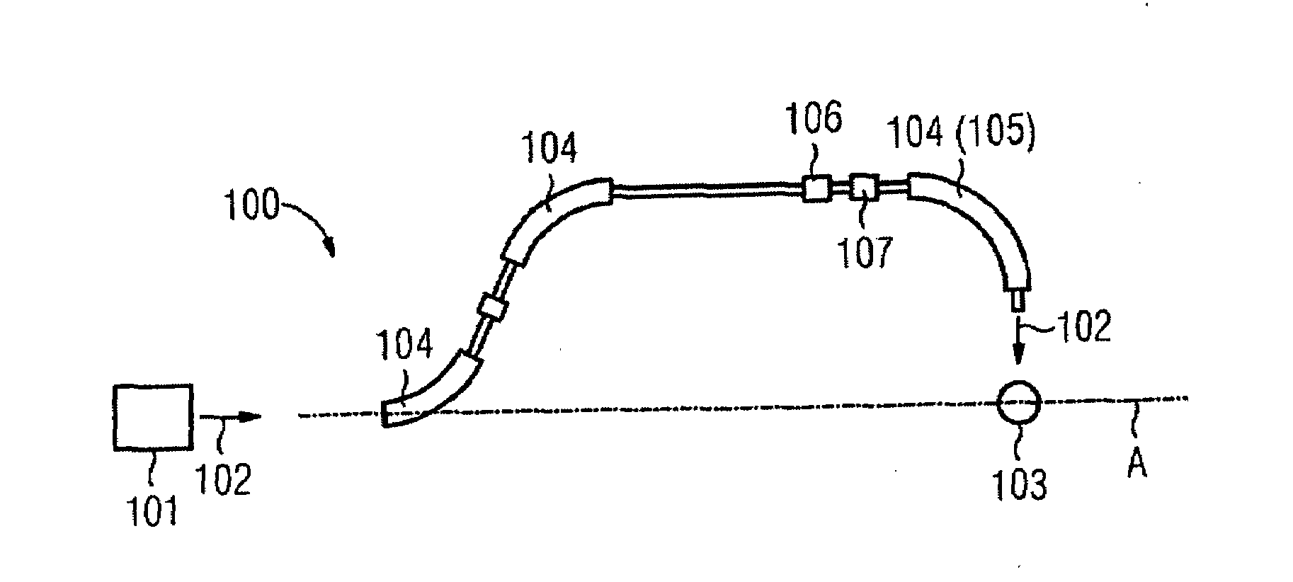
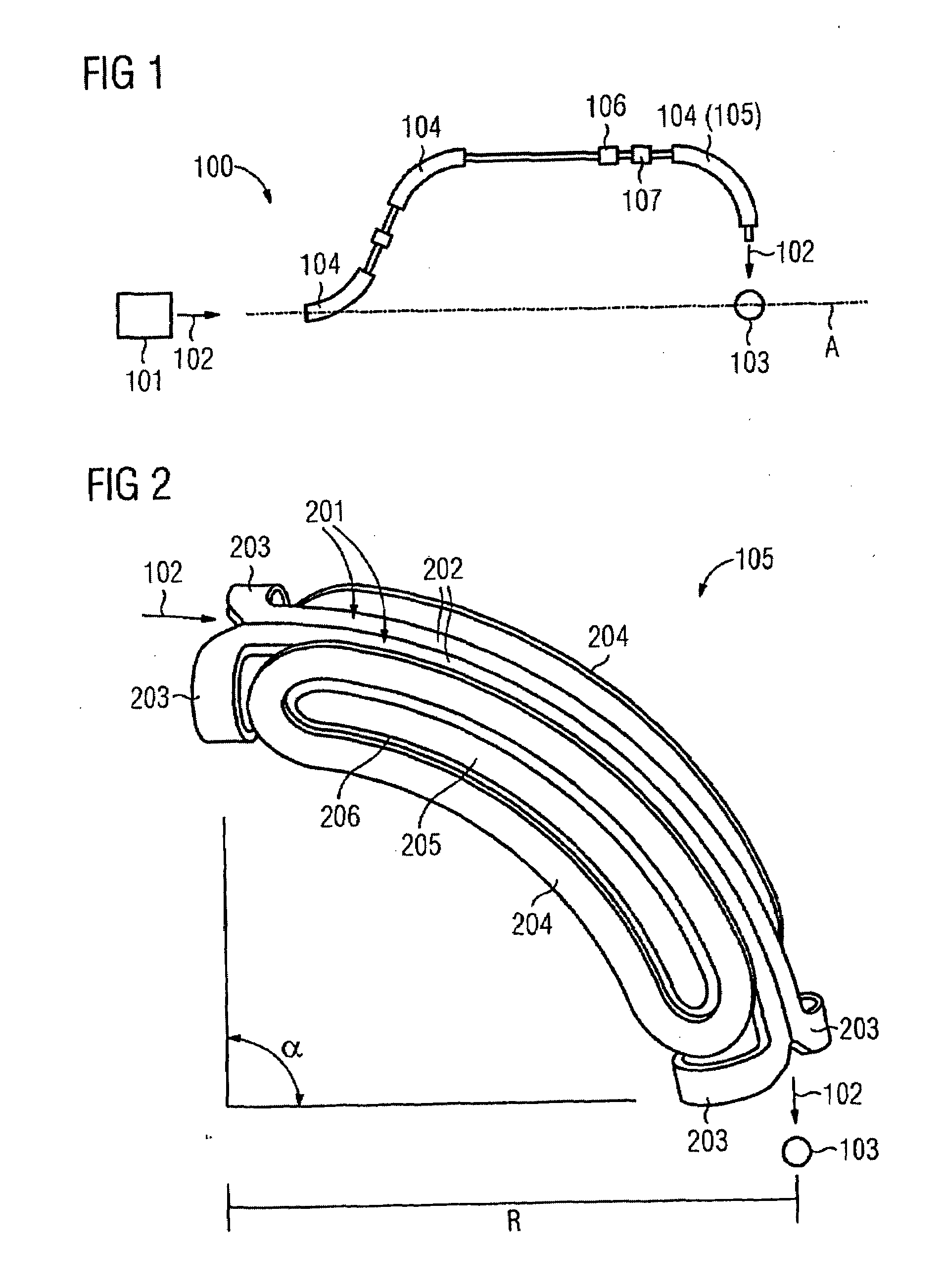
[0031]FIG. 1 shows a radiation treatment system 100 with a stationary particle source 101. Originating at the particle source 101, a beam of electrically charged particles is shot (guided) into a gantry along a particle path 102. The gantry includes a plurality of deflection and / or beam control magnets 104, 105, an X scanner magnet 106, and a Y scanner magnet 107. The gantry is rotatable about an axis A of rotation, so that the beam of electrically charged particles, along its particle path 102, upon the rotation of the gantry always intersects the axis A of rotation at a fixed point, the isocenter 103.

[0032]FIG. 2 shows a beam control magnet 105, in which components other than the coils of the magnet system have been left out. The beam control magnet 105 serves to deflect a beam of electrically charged particles along a particle path 102. The trajectory described by the charg...


PUM


Abstract

A radiation treatment system with a beam control magnet for deflecting a beam of electrically charged particles along a curved particle path. The beam control magnet is subdivided along a parting plane perpendicular to the direction of the particle path into a first region and a second region. The quadrupole moments of the beam control magnet have different signs in the first region and the second region.

Description

[0001]This application claims the benefit of DE 10 2007 046 508.6, filed Sep. 28, 2007, which is hereby incorporated by reference.BACKGROUND[0002]The present embodiments relate to a radiation treatment system having a beam control magnet for deflecting a stream of electrically charged particles.[0003]German Patent Application 10 2006 018 635.4, which was not published prior to the filing date of the present application, describes a radiation treatment system. The radiation treatment system includes a coil system. The coil system includes two saddle-shaped primary coils, with side parts elongated in the direction of the particle path and with end parts bent open relative to the beam control plane, two at least largely flat secondary coils, curved in bananalike fashion and disposed between the end parts of the primary coils, with side parts elongated in the direction of the particle path and with curved end parts that each surround one inner region, and two at least largely flat addit...

Claims


Application Information

Patent Timeline
IPC IPC(8): H01J3/14H01J5/18
CPCA61N2005/1087H05H7/04G21K1/093
Inventor DIEHL, DIRKGUMBRECHT, RENESCHNEIDER, EVA
Owner SIEMENS AG
Learn More