Fuel Cell, Method and Apparatus for Manufacturing Fuel Cell

Inactive Publication Date: 2009-04-02
TOYOTA JIDOSHA KK
View PDF6 Cites 9 Cited by
  • Summary
  • Abstract
  • Description
  • Claims
  • Application Information

AI Technical Summary

Benefits of technology

[0006]In view of the above, the invention provides a fuel cell capable of suppressing fluctuations in the length of a fuel cell stack or thickness of a single cell, a method of manufacturing such a fuel cell, and an apparatus for manufacturing the fuel cell.
[0008]According to the foregoing first aspect, an aging process is applied to the cell module before it is used so that creep of the stack during use of the fuel cell can be reduced. As a result, the necessary tightening load of the fuel cell stack can be maintained throughout the target lifetime of the cell module. This is because creep initially progresses rapidly (e.g., primary creep) but then slows down afterwards (e.g., steady-state creep). Thus, inducing creep through the initial stage may therefore be considered a rational approach because the process of progressing through initial creep can be completed relatively quickly.
[0009]Also, a manufacturing method of a fuel cell according to a second aspect of the invention includes an aging step for progressing through initial creep by applying at least a compression load to the cell module. According to this second aspect, providing an aging step for progressing through initial creep by applying at least a compression load to a cell module enables creep of the stack during use of the fuel cell to be reduced. As a result, the necessary tightening load of the fuel cell stack can be maintained throughout the target lifetime of the cell module. As described in the preceding paragraph, the process of progressing through initial creep can be completed quickly, as deformation during primary creep occurs rapidly before stabilizing.
[0010]In the aging step, the cell module may be subjected to a thermal load in addition to the compression load. In addition, a compression load may also be applied for a predetermined period of time that is shorter than the target lifetime of the product. By applying a thermal load in addition to the compression load in the aging step, it is possible to both accelerate the progression of creep more so than when only the compression load is applied, and reduce creep during actual use in which there is a thermal load. In addition, it is possible to finish aging in a shorter period of time.
[0012]The thermal load may be applied by running a heated fluid through a fluid flow path of the cell module. Pressure may be applied to the heated fluid. Applying the thermal load by running a heated fluid through a fluid flow path of the cell module enables the thermal load to be applied easily, as well as in a state close to the state in which the cell module is actually used. Further, applying pressure to the heated fluid is effective for accelerating creep of the separator when the separator is a carbon separator.

Problems solved by technology

When a tightening load is applied to the fuel cell stack over an extended period of time, however, creep of an adhesive layer between separators of the cell module or the like causes the fuel cell stack to contract in the direction in which the cell modules are stacked.
If a carbon separator is used, creep of the binder resin of the separator itself may occur.
If the extent of contraction exceeds the amount of fluctuation in tightening load that can be compensated for by the disc spring, it will not be possible to prevent further loosening or decrease in tightening force.

Method used


Image

  • Fuel Cell, Method and Apparatus for Manufacturing Fuel Cell
  • Fuel Cell, Method and Apparatus for Manufacturing Fuel Cell
  • Fuel Cell, Method and Apparatus for Manufacturing Fuel Cell

Examples


first example embodiment

FIG. 1

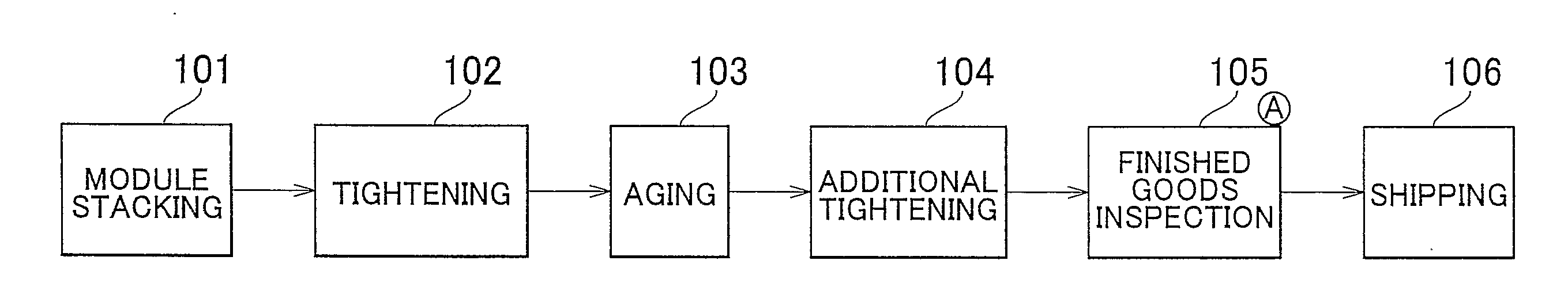
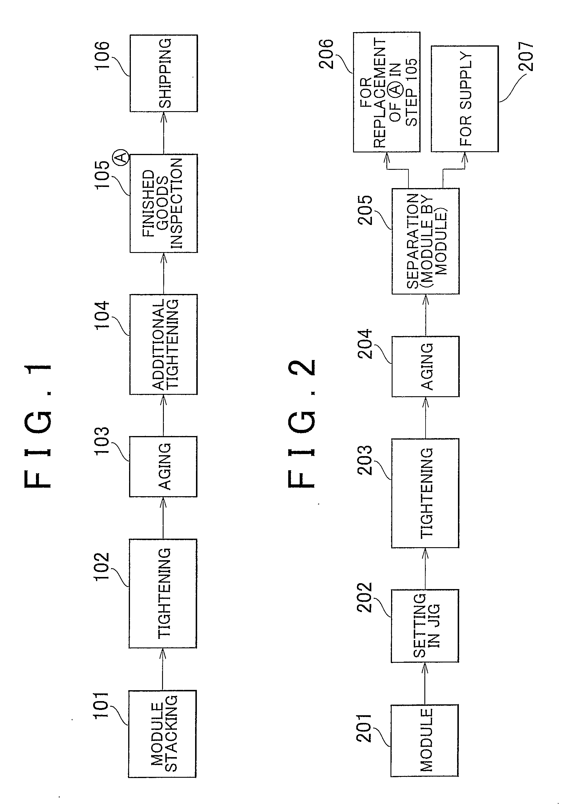
[0066]The fuel cell (the stack 23 or the single cell 10) according to the first example embodiment of the invention is manufactured according to FIG. 1. Also, the manufacturing method of the fuel cell (the stack 23 or the single cell 10) according to the first example embodiment of the invention is a manufacturing method according to the steps shown in FIG. 1. The manufacturing method of a fuel cell (the stack 23 or the single cell 10) according to the first example embodiment of the invention is a manufacturing method of a fuel cell, which includes an aging step 103 for progressing through initial creep by applying at least a compression load to a cell module after stacking, and an additional tightening step 104 for additionally tightening the fuel cell stack 23 after the aging step 103.

[0067]In the fuel cell (the stack 23 or the single cell 10) and the manufacturing method thereof according to the first example embodiment of the invention, as shown in FIG. 1, the cell module...

second example embodiment

FIG. 2

[0071]The fuel cell (the stack 23 or the single cell 10) according to the second example embodiment of the invention is manufactured according to FIG. 2. Also, the manufacturing method of the fuel cell (the stack 23 or the single cell 10) according to the second example embodiment of the invention is a manufacturing method according to the steps shown in FIG. 2. The manufacturing method of a fuel cell (the stack 23 or the single cell 10) according to the second example embodiment of the invention includes an aging step for progressing through initial creep by applying at least a compression load to a cell module before stacking, and an incorporating step for incorporating the cell module into the stack after the initial creep has been progressed.

[0072]With the fuel cell (the stack 23 or the single cell 10) and the manufacturing method thereof according to the second example embodiment, as shown in FIG. 2, cell modules are supplied in step 201. The cell module is set, either in...


PUM

PropertyMeasurementUnit
Temperatureaaaaaaaaaa
Timeaaaaaaaaaa
Thicknessaaaaaaaaaa

Abstract

A fuel cell (stack or a single cell) includes a cell module to which an aging process that progresses initial creep has been applied such that creep during use is reduced compared with a cell module to which the aging process has not been applied. A manufacturing method of a fuel cell (stack or a single cell) includes an aging step for progressing through initial creep by applying at least a compression load to a cell module.

Description

BACKGROUND OF THE INVENTION[0001]1. Field of the Invention[0002]The invention relates to a fuel cell, a method and apparatus of manufacturing the fuel cell.[0003]2. Description of the Related Art[0004]Japanese Patent Application Publication No. JP-A-2002-35985 discloses a fuel cell stack. This fuel cell stack has an elastic member provided at one end thereof to compensate for changes in tightening load. In particular, the gradual loosening or reduction in tightening force, caused by, for example, thermal expansion and contraction, or creep in the lengthwise direction of the stack. The elastic member may be a disc spring, for example, which is able to compensate for changes in the tightening load by adjusting to changes in the lengthwise direction of the fuel cell stack that are within the effective stroke range of the disc spring.[0005]When a tightening load is applied to the fuel cell stack over an extended period of time, however, creep of an adhesive layer between separators of t...

Claims


Application Information

Patent Timeline
IPC IPC(8): H01M2/02B65B11/52
CPCH01M8/04074H01M8/248Y10T29/49108Y02E60/50H01M8/2485H01M8/2404Y02P70/50H01M8/2483
Inventor AKIMOTO, NAOMICHI
Owner TOYOTA JIDOSHA KK
Why Eureka
Try Eureka