
Signal modulation method, signal modulation apparatus, electronic device, and computer program product

Inactive Publication Date: 2009-04-02
FUJITSU LTD
View PDF5 Cites 1 Cited by
  • Summary
  • Abstract
  • Description
  • Claims
  • Application Information

AI Technical Summary

Benefits of technology

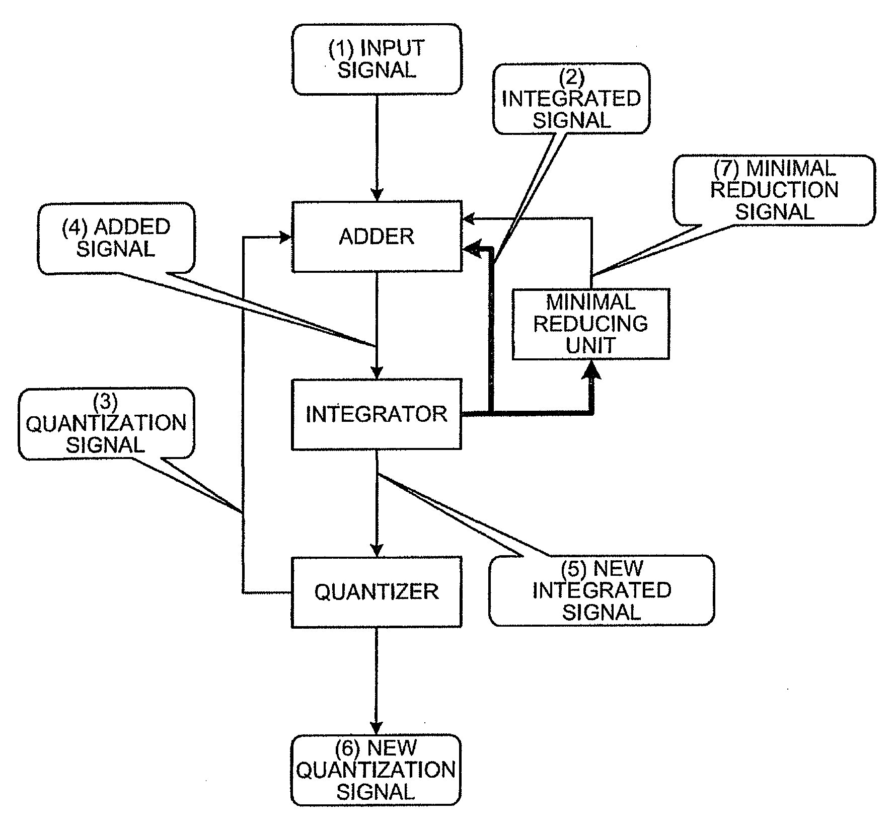
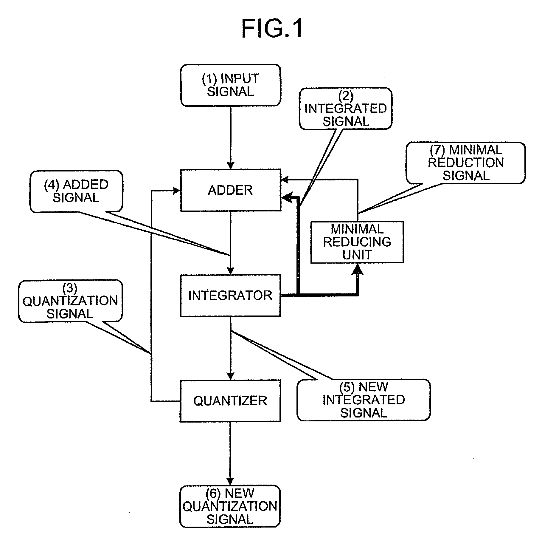
[0015]According to an aspect of the present invention, a signal modulation method by an electronic device including a quantizer, an integrator, and an adder, includes generating an added signal with the adder by subtracting a quantization signal returned by the quantizer from an input signal and by adding an integrated signal returned by the integrator to the input signal; generating a new integrated signal with the integrator by returning a previously self-generated and stored integrated signal to the adder and by integrating the added signal generated by the adder; generating a new quantization signal with a quantizer by quantizing the new integrated signal generated by the integrator; and minimally reducing the integrated signal returned to the adder from the integrator.
[0016]According to another aspect of the present invention, a signal modulation apparatus modulates an input signal to a quantization signal. The signal modulation apparatus includes a quantizer; an integrator; an adder that generates an added signal by subtracting the quantization signal returned by the quantizer from the input signal, and by adding an integrated signal returned by the integrator to the input signal; and a minimal reducing unit. The integrator returns a previously self-generated and stored integrated signal to the adder, generates a new integrated signal by integrating the added signal generated by the adder, and stores therein the new integrated signal generated. The quantizer returns a previously self-generated quantization signal to the adder, and generates a new quantization signal by quantizing the new integrated signal generated by the integrator. The minimal reducing unit minimally reduces the integrated signal returned to the adder from the integrator.
[0017]According to still another aspect of the present invention, an electronic device modulates an input signal to a quantization signal. The electronic device includes a quantizer; an integrator; an adder that generates an added signal by subtracting the quantization signal returned by the quantizer from the input signal, and by adding an integrated signal returned by the integrator to the input signal; and a minimal reducing unit. The integrator returns a previously self-generated and stored integrated signal to the adder, generates a new integrated signal by integrating the added signal generated by the adder, and stores therein the new integrated signal generated, the quantizer returns a previously self-generated quantization signal to the adder, and generates a new quantization signal by quantizing the new integrated signal generated by the integrator, and the minimal reducing unit minimally reduces the integrated signal returned to the adder from the integrator.

Problems solved by technology

In the related art, there is a problem that output noise generated by receiving a silent signal cannot be reduced.
Therefore, an audible quantization signal is generated, thereby occasionally generating noise as a consequence.
H07-7435, not only the installation is difficult, but noise is sometimes generated, even if the random signal receives the silent signal.

Method used


Image

  • Signal modulation method, signal modulation apparatus, electronic device, and computer program product
  • Signal modulation method, signal modulation apparatus, electronic device, and computer program product
  • Signal modulation method, signal modulation apparatus, electronic device, and computer program product

Examples


first embodiment

[0032]At this time, the minimal reducing unit of the signal modulation apparatus generates a minimal reduction signal (see (7) in FIG. 1) that minimally reduces the integrated signal from the integrated signal returned by the integrator, and minimally reduces the integrated signal returned to the adder from the integrator.

[0033]In this manner, the signal modulation apparatus according to the first embodiment, as the main characteristic, can reduce the output noise generated by receiving the silent signal, by minimally reducing the integrated signal returned to the adder from the integrator, by the minimal reducing unit.

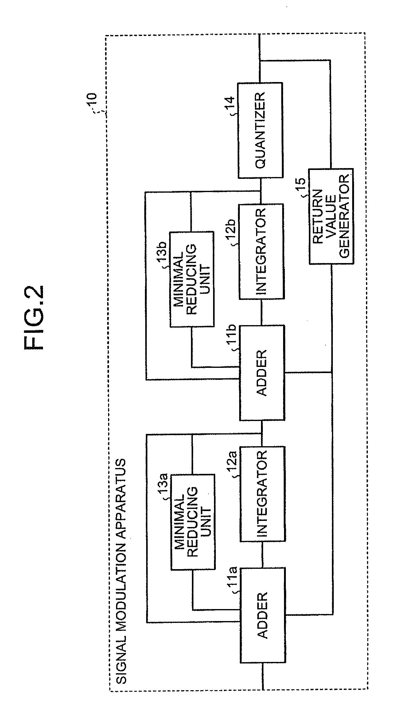
[0034]A configuration of a signal modulation apparatus 10 will now be explained with reference to FIG. 2. FIG. 2 is a block diagram of the configuration of the signal modulation apparatus. As shown in FIG. 2, the signal modulation apparatus 10 includes adders 11a and 11b, integrators 12a and 12b, minimal reducing units 13a and 13b, a quantizer 14, and a return value ...

second embodiment

[0067]A configuration of a CODEC macro 20 will now be explained with reference to FIG. 4. FIG. 4 is a block diagram of the configuration of a CODEC macro.

[0068]As shown in FIG. 4, the CODEC macro 20 includes an analog-digital converter 21 and a digital-analog converter 22. The analog-digital converter 21 includes a pre-filter 23, a signal modulation apparatus 10a, and a digital filter 24a to convert an analog signal to a digital signal. It will be explained under the assumption that the pre-filter 23 and the signal modulation apparatus 10a execute each processing by hardware processing, and the digital filter 24a executes the processing by software processing that executes a predetermined algorithm on a computer.

[0069]The pre-filter 23 corresponds to a low-pass filter that removes a frequency band equal to or more than a predetermined frequency from the input signal, and anti-aliases the analog signal. In other words, the pre-filter 23 suppresses folded noise generated by the signa...

third embodiment

[0080]A configuration of a mobile terminal will now be explained with reference to FIG. 5. FIG. 5 is a block diagram of the configuration of the mobile terminal.

[0081]As shown in FIG. 5, a mobile terminal 30 includes the CODEC macro 20, an analog signal input unit 31, an analog signal output unit 32, an antenna 33, a digital base band (DBB) macro 34, and an application (APL) chip 36.

[0082]The CODEC macro 20 modulates the analog signal to the digital signal, and the digital signal to the analog signal. More specifically, the CODEC macro 20 corresponds to the CODEC macro 20 according to the second embodiment, modulates the analog signal to the digital signal by the analog-digital converter 21, and modulates the digital signal to the analog signal by the digital-analog converter 22.

[0083]The analog signal input unit 31 receives the analog signal from outside of the mobile terminal 30. More specifically, the analog signal input unit 31 corresponds to an analog terminal that receives th...


PUM


Abstract

A signal modulation method by an electronic device which includes a minimal reducing unit that minimally reduces an integrated signal returned to an adder from an integrator.The signal modulation method includes generating an added signal with the adder. The signal modulation method further includes generating a new integrated signal with the integrator by returning a previously self-generated and stored integrated signal to the adder, and by integrating the added signal generated by the adder.The signal modulation method further includes generating a new quantization signal with a quantizer by quantizing the new integrated signal generated by the integrator.

Description

BACKGROUND OF THE INVENTION[0001]1. Field of the Invention[0002]The present invention relates to a signal modulation method, a signal modulation apparatus, an electronic device, and a computer program product.[0003]2. Description of the Related Art[0004]Signal modulation apparatuses (sigma-delta modulation apparatus and delta-sigma modulation apparatus) that modulate an input signal, to carry out an analog-digital conversion and a digital-analog conversion have been widely applied to electronic devices such as audio equipment, communication equipment (for example, audio coder-decoder (CODEC) for mobile terminals), and measuring equipment that require highly accurate signal processing. Related technology has been disclosed in Japanese Patent Application Laid-open No. 2002-502565, Japanese Patent Application Laid-open No. H07-7435, Japanese Patent Application Laid-open No. 2002-314425, and Japanese Patent Application Laid-open No. 2006-42315.[0005]A related-art signal modulation appar...

Claims


Application Information

Patent Timeline
IPC IPC(8): H03M3/02
CPCH03M3/442
Inventor HATAE, KAZUHIKOOHTOMO, YASUOSATO, MASASHIAWATA, YUTAKA
Owner FUJITSU LTD
Learn More