
NMR Measurement Method

Inactive Publication Date: 2014-03-13
JEOL RESONANCE
View PDF0 Cites 0 Cited by
  • Summary
  • Abstract
  • Description
  • Claims
  • Application Information

AI Technical Summary

Benefits of technology

The present invention is a method that uses differences in RF magnetic field strength to alleviate the problem of setting the number of accumulations and achieve background suppression with fewer phase cycling steps. This method reduces background-derived signals from the material of the NMR probe by applying an RF pulse sequence consisting of a 90° pulse and one or more following 180° pulses to a sample and detecting the NMR signals. The detected NMR signals are accumulated while varying the RF phase of each pulse in accordance with a cogwheel phase-cycling scheme. This approach allows for more flexibility in setting the accumulation number and achieves background suppression with fewer phase cycling steps.

Problems solved by technology

These create a new background problem when 27Al NMR measurements or 29Si NMR measurements are performed.
In many cases, however, the background signal is suppressed at the expense of detection of any other nuclide.
Consequently, any effective method that can be applied to every nuclide is unavailable.
In particular, the background signal cannot be removed until 64 experimental steps are performed.
However, the greatest problem is that a large number of phase cycling steps are required.
That is, an excessive number of accumulations are necessary to complete the phase cycling process.
This presents the problem that the measurement time is prolonged unnecessarily.
This problem is often encountered in 19F NMR measurements.

Method used


Image

  • NMR Measurement Method
  • NMR Measurement Method
  • NMR Measurement Method

Examples


embodiment 1

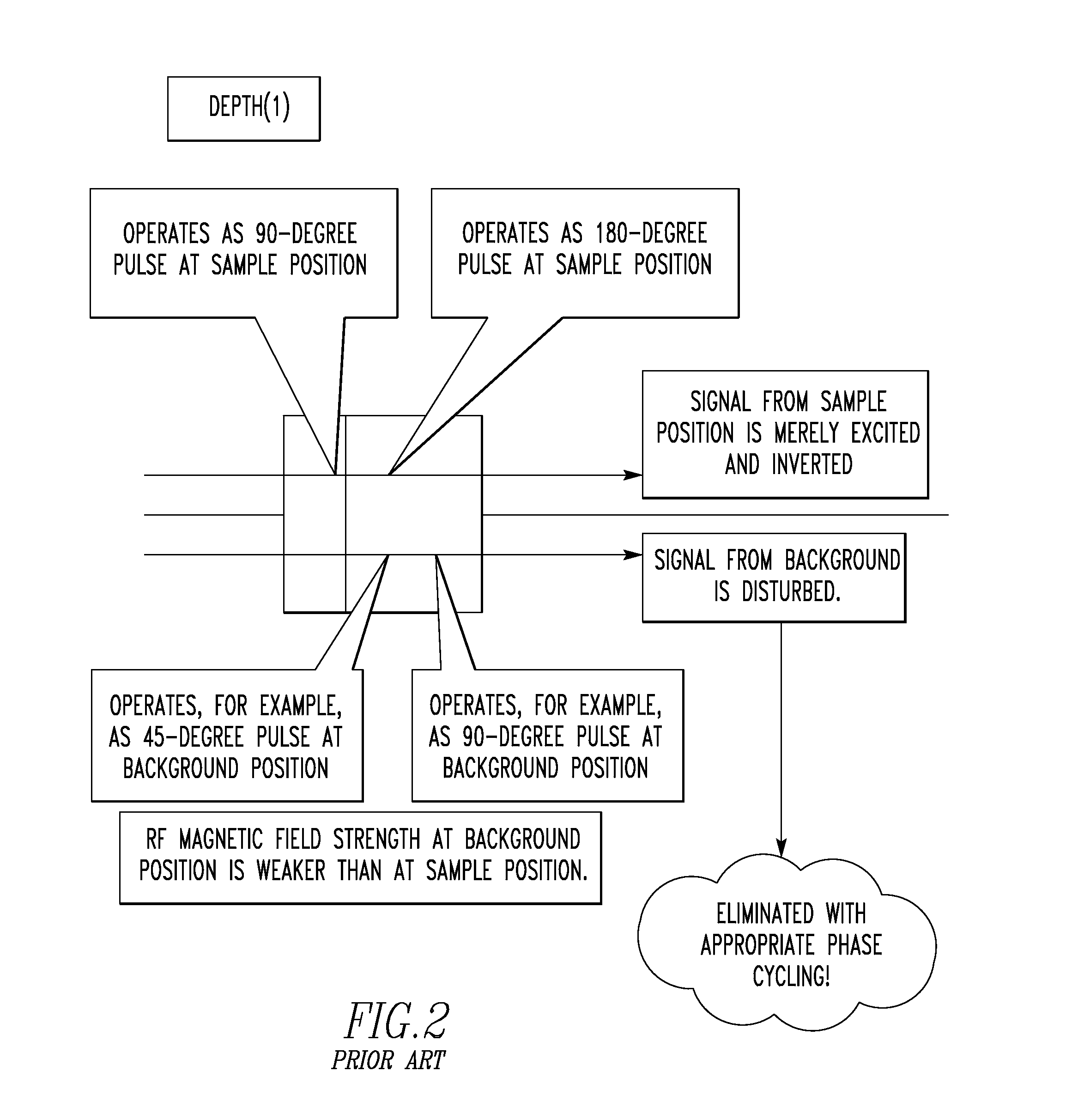
[0033]We have discovered that the approach DEPTH taken while paying attention to differences in RF magnetic field strength B1 can be essentially attributed to coherence selection.

[0034]On the other hand, cogwheel phase cycling has been proposed as one technique for reducing the number of phase cycling steps while taking notice of coherence selection (see M. H. Levitt, P. K. Madhu, C. E. Hughes, Journal of Magnetic Resonance, vol. 155, pp. 300-306 (2002)). In this cogwheel phase cycling, a pulse sequence consisting of plural pulses is divided into plural blocks. Whenever a measurement is performed, the RF phases of the blocks are simultaneously increased by their respective factors (at their respective ratios). This technique yields the same advantageous effects as the prior art phase cycling although the number of phase cycling steps is fewer.

[0035]This cogwheel phase cycling has been used, for example, in MQ-MAS (multiple-quantum magic-angle spinning) for solid-state NMR spectrosco...

embodiment 2

[0070]The background signal suppression according to the present invention is achieved by applying n 180° pulses to transverse magnetization. In embodiment 1, 180° pulses are applied to transverse magnetization generated by a 90° pulse. In embodiment 2, the technique is further generalized. In embodiment 2, combinations of other pulse (e.g., a 270° pulse) or pulse sequence capable of generating transverse magnetization are set forth. If this pulse or pulse sequence is set to a single 90° pulse, then embodiment 1 is obtained.

[0071]Where n of DEPTHn is an odd number, a pulse sequence generating transverse magnetization needs a magnetization of +1. Where n is an even number, a pulse sequence generating transverse magnetization needs a magnetization of −1. An example of DEPTH2 is now discussed.

[0072]A pulse sequence generating transverse magnetization creates a magnetization of −1. First, incompleteness of this pulse sequence is neglected. That is, it is assumed that immediately after t...


PUM


Abstract

A method of NMR measurement which achieves background suppression based on a technique employing differences in RF magnetic field strength while alleviating the problem that less latitude is allowed in setting the number of signal accumulations. This method suppresses a background-derived signal emanating from the material of an NMR probe. The method starts with applying an RF pulse sequence consisting of a 90° pulse and subsequent one or more 180° pulses to a sample to induce an NMR signal and detecting the signal. This application is repeated while varying the RF phases of the pulses to induce NMR signals in accordance with a cogwheel phase-cycling scheme to induce NMR signals. The NMR signals are detected. The detected NMR signals are accumulated.

Description

BACKGROUND OF THE INVENTION[0001]1. Field of the Invention[0002]The present invention relates to a method of nuclear magnetic resonance (NMR) measurement and, more particularly, to a method used to suppress unwanted signals, known as a background signal. Often, an NMR spectrum is observed in which signals arising from substances (principally the material of the NMR probe) other than the sample under investigation are superimposed on the signal arising from the sample. Usually, the superimposed signals are called the background signal. Where the signal arising from the sample is sufficiently strong, a week background signal presents no serious problems. However, where a weak signal is observed as encountered when a trace amount of sample is measured, great problems take place.[0003]Furthermore, even when a sufficient amount of sample under investigation exists, if a nuclide (such as 19F) that is also contained in large amounts in the material of the probe is measured, the background ...

Claims


Application Information

Patent Timeline
IPC IPC(8): G01R33/54
CPCG01R33/54G01R33/4608G01R33/4616
Inventor NISHIYAMA, YUSUKEFREY, MICHAEL H.
Owner JEOL RESONANCE
Learn More