
Detection device and method

a detection device and detection method technology, applied in the direction of magnetic particle measurement, magnetic measurement, magnetic beads labelled molecules, etc., can solve the problem of relatively slow detection in the frequency domain, and achieve the effect of eliminating the sweep frequency of the measuring field, increasing the magnetisation of the sample, and decreasing the magnetisation

Active Publication Date: 2009-04-02
ACREO SWEDISH ICT
View PDF5 Cites 37 Cited by
  • Summary
  • Abstract
  • Description
  • Claims
  • Application Information

AI Technical Summary

Benefits of technology

[0005]One object of the present invention is to measure small magnetic signals from samples with low magnetic content or low magnetic properties. Another object of the present invention is to measure the increase of the magnetisation of the sample when the field is applied and the decrease of magnetisation when the field is turned off. Yet another object of the invention is to eliminate frequency sweep of a measuring field.
[0006]An important advantage of the sample response measurements according to the invention is its speed; the measurements are much faster than the previously described technique based on the sweeping of the frequency of the excitation field.
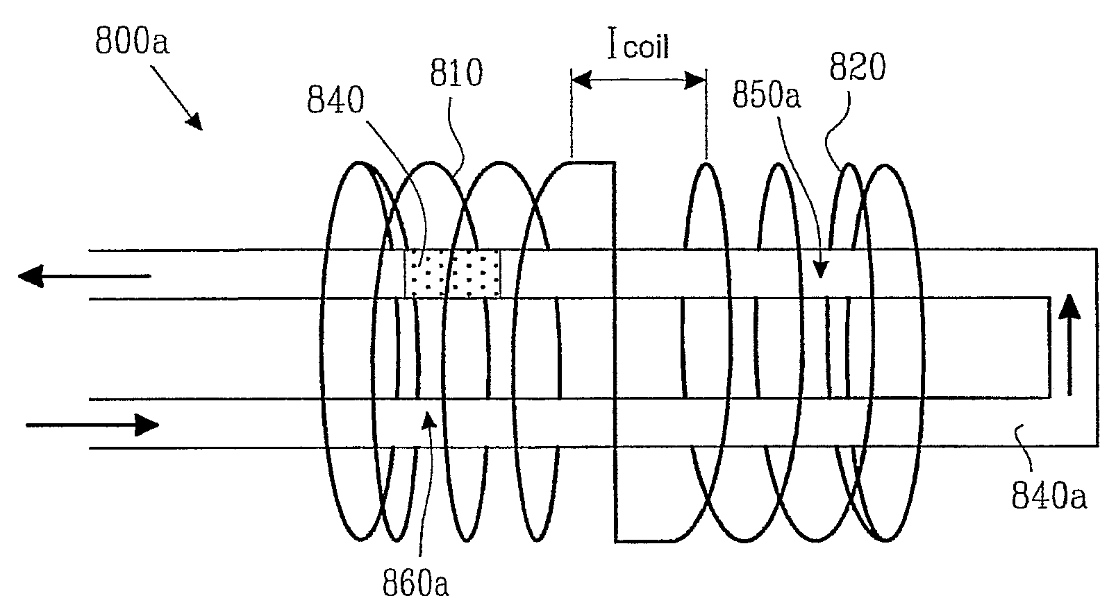
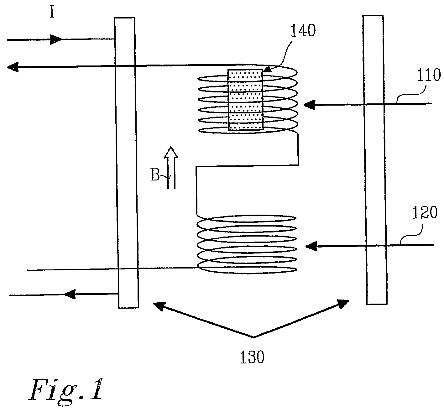
[0015]Preferably, a magnetic signal is measured first from a measurement with a sample in one of the coils and then another measurement of the sample in the other coil. A total voltage detected when the sample is in the first coil is V1+Vbackground and the total voltage detected when the sample is in the second coil is −V2+Vbackground, and a difference of the two measurements results in V1+ V2 which eliminates a background noise and the mean value of V1+V2 represents a signal from the sample.

Problems solved by technology

Moreover, the detection in the frequency domain is usually relatively slow and requires changes of the sample position from one detection coil to another.

Method used


Image

  • Detection device and method
  • Detection device and method
  • Detection device and method

Examples


example 1

[0075]Consider particles covered with biotin added to a solution with (strept-, neutro-, etc.) avidin. Since these molecules each have multiple biotin binding sites it is possible to determine their amount in solution by monitoring the agglomeration rate.

example 2

[0076]Consider particles that are covered with (strept-, neutro-, etc.) avidin. If the target molecule is able to form multiple bonds with biotin and these target molecules with multiply bound biotins are exposed to avidin covered particles it is very probable that particle clustering will occur.

example 3

[0077]Assume that the concentration of a known DNA sequence is required that is characteristic of for example TBC or HIV or other bacterias, cells, etc. It is possible then to extract DNA from the cell or micro-organism, cut into suitable sequence lengths and amplify it. Then it is possible to add to the solution containing the target DNA strands particles covered with suitable complementary single strands, split the double target strands into a single ones and allow the strands on the particles to hybridise with the target strands in solution.

[0078]It is possible to monitor hydrodynamic volume changes either in the time domain or in the frequency domain.

[0079]If however the cut DNA pieces are long enough to be able to hybridize to the two different DNA single strands on the particles then the clustering will occur. In this case, it is possible to monitor the agglomeration in the time domain. The agglomeration rate will be a measure of the concentration of such long DNA strands in s...


PUM


Abstract

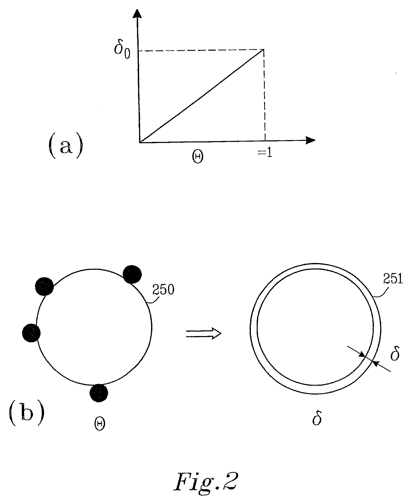
The present invention relates to method and device for detecting changes of a magnetic response of at least one magnetic particle in a carrier fluid. The method comprises: using a measuring procedure comprising measuring the characteristic rotation time of said magnetic particle, said measuring procedure further involving measuring Brownian relaxation in said carrier fluid under influence of an external pulsed excitation magnetic field, and based on said influence of said external pulsed excitation magnetic field measuring a hydrodynamic volume of a particle or a change in a hydrodynamic volume of the particle change upon modification of an effective volume of the particle or its interaction with said carrier fluid by detecting change of magnetization of the particle with time by monitoring change of an output signal in detection coil.

Description

TECHNICAL FIELD OF THE INVENTION[0001]Detection of Brownian relaxation times by measuring the dynamic magnetic susceptibility (sinus excitation) and the magnetic relaxation (pulsed excitation)BACKGROUND OF THE INVENTION[0002]Brownian relaxation of a magnetic particle system with thermally blocked magnetic single domains (in the particles) can be detected by sweeping the frequency of the measuring field and measure the magnetic response, i.e. the real and imaginary part of the magnetic response, see for example WO 03 / 019188, by the same applicant and incorporated herein by reference. At the characteristic Brownian relaxation frequency the real part of the magnetic response decreases and the imaginary part exhibit a maximum. From the frequency dependent magnetic response the Brownian relaxation frequency can be determined. This method may be sensitive since it is possible to use the sensitivity of the lock-in amplifier technique in order to detect the magnetic response from the detect...

Claims


Application Information

Patent Timeline
Patent Type & Authority Applications(United States)
IPC IPC(8): G01R33/12G01R35/00
CPCG01R33/12G01R33/16G01R33/1276G01R33/1269
Inventor KROZER, ANATOLJOHANSSON, CHRISTERBLOMGREN, JAKOBPETERSSON, KAROLINAILVER, DAGPRIETO-ASTALAN, ANDREAJONASSON, CHRISTIAN
Owner ACREO SWEDISH ICT
Learn More