
Fryer

a technology of fryer and operating panel, which is applied in the field of fryer, can solve the problems of poor operation of the operating panel and unnecessary increase of cost, and achieve the effects of simple structure, small increase of cost, and effective suppression of the temperature increase of the operating panel

Inactive Publication Date: 2009-04-02
PALOMA
View PDF11 Cites 7 Cited by
  • Summary
  • Abstract
  • Description
  • Claims
  • Application Information

AI Technical Summary

Benefits of technology

[0007]An object of the invention is to provide a fryer capable of suppressing effectively increase in temperature of an operational panel with simple structure in which increase of cost is small and without detriment to usability.

Problems solved by technology

Accordingly, when an operator operates the operational panel, the increase in temperature of the operational panel gives him discomfort, and may cause poor operation of the operational panel.
However, the provision of the fan causes unnecessary increase of cost, and the installation of the operational panel apart from the oil vat causes inconvenience because the operational position becomes far from a cooker.

Method used


Image

  • Fryer
  • Fryer
  • Fryer

Examples


embodiment 1

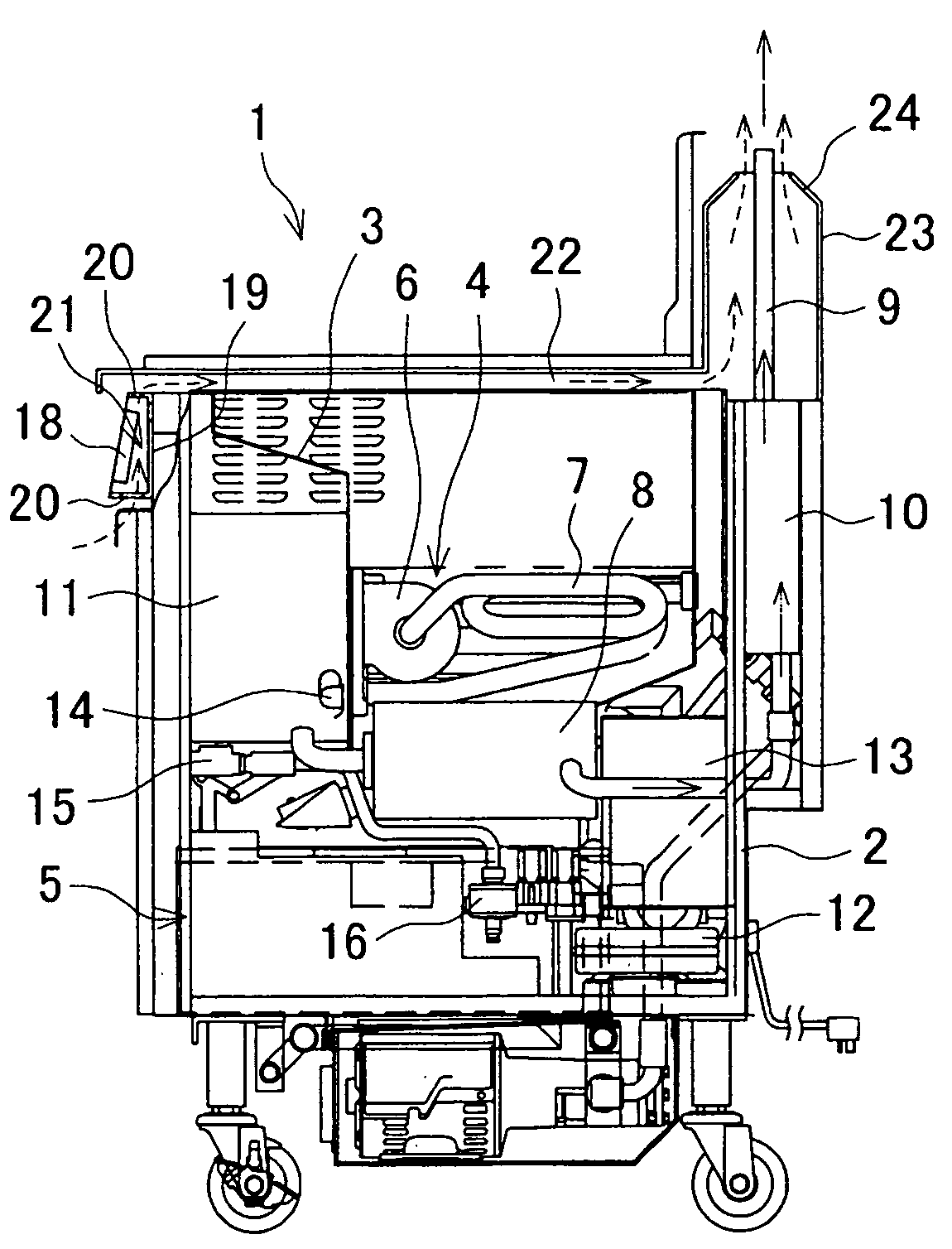
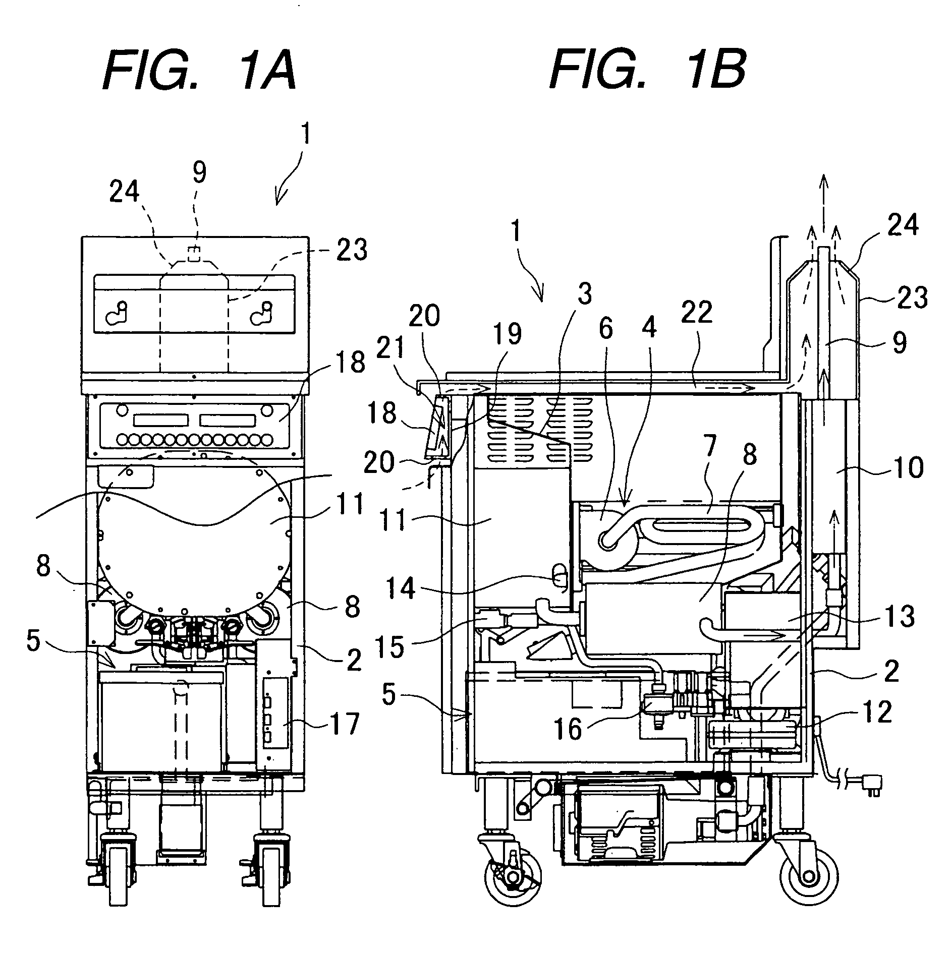
[0013]FIGS. 1A and 1B are explanatory views showing an example of a fryer, in which FIG. 1A shows a front view and FIG. 1B shows a side view. A fryer 1 includes, in a housing 2, an oil vat 3 filled with oil, a pulse burner 4 as a combusting and heating unit for heating the oil in this oil vat 3, and an oil cleaner 5 for filtering the oil. The pulse burner 4 includes a combustion exhaust system that includes: a combustion chamber 6 which is provided in the oil vat 3 and combusts mixed gas of fuel gas and combustion air; a tail pipe 7 through which combustion gas from the combustion chamber 6 passes; a de-coupler 8, 8 connected to the downstream side of the tail pipe 7 and provided on both sides of the oil vat 3; and an exhaust pipe 9 which is connected to the downstream side of the de-coupler 8, 8 and installed upright at the rear of the housing 2. Reference numeral 10 is a muffler provided midway of the exhaust pipe 9.

[0014]Reference numeral 11 is an air chamber provided at the outs...

embodiment 2

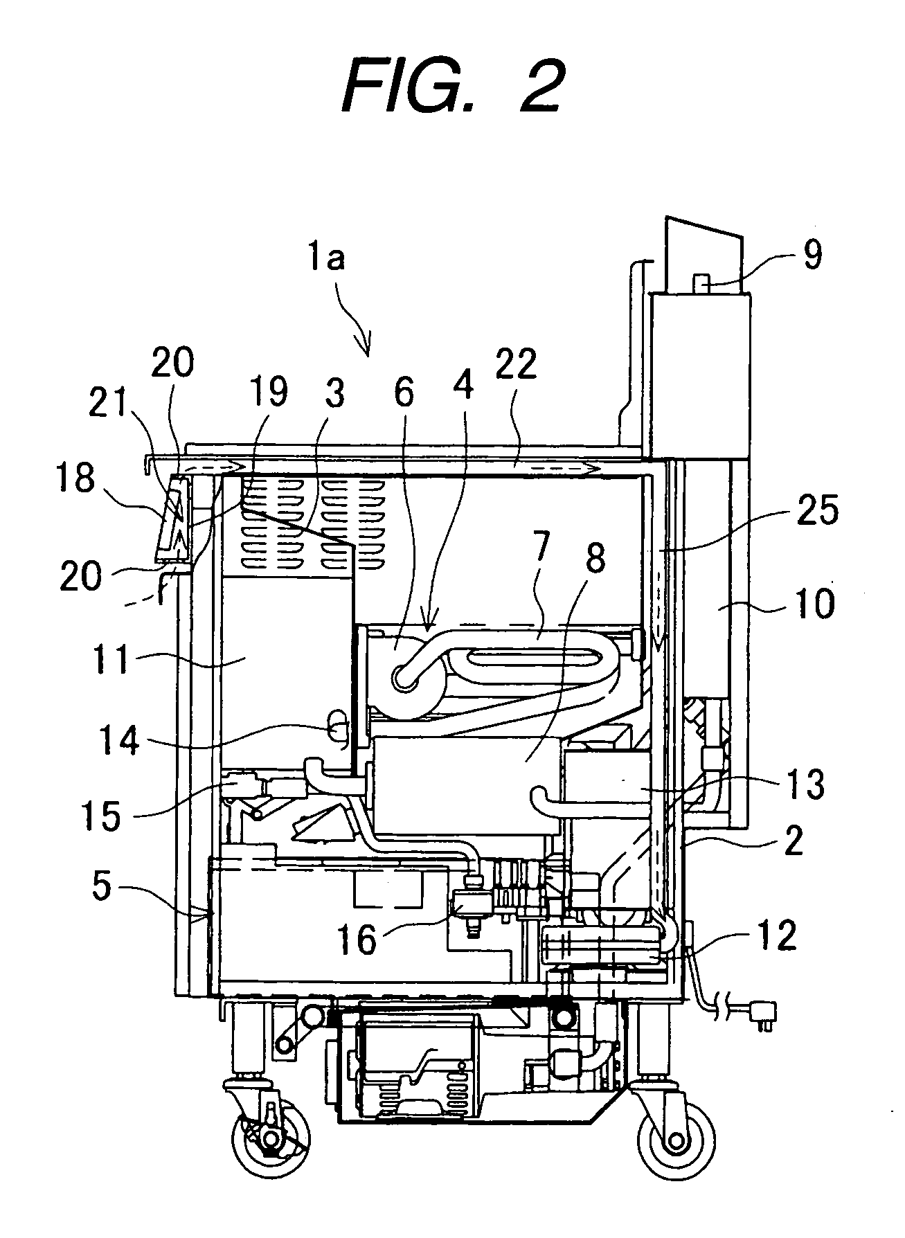
[0023]Next, another embodiment of the invention will be described. The same components as those in the first embodiment are denoted by the same reference numerals and their repeated explanation is omitted.

[0024]In a fryer la shown in FIG. 2, left and right air passages 22 provided at the upper portion of a housing 2 are extended respectively through hoses 25 and connected to a fan 12. Namely, a cooling path 21 and air passages 22 are connected to an air supply system of a pulse burner 4.

[0025]Accordingly, as soon as an operation switch of a fry controller 18 is turned on, a burner controller 17 rotates the fan 12 for a predetermined time for purpose of air supply. Thereafter, the burner controller 17 operates the pulse burner 4 to execute ON / OFF control. At this time, by exhaust of combustion exhaust gas from a combustion chamber 6, the inside of the combustion chamber 6 is put in a negative pressure state. Therefore, fuel gas is taken into the combustion chamber 6, while the outsid...


PUM


Abstract

A fryer includes: a housing; an oil vat; a combusting and heating unit; an operational panel provided at a front face of the housing; and an exhaust pipe provided at a rear of the oil vat. A cooling path is defined at a rear of the operational panel in the housing. An external pipe is provided at a rear of the housing to surround the exhaust pipe and has an exhaust port of which the sectional opening area is narrowed at an upper end of the exhaust pipe. An air passage is defined by the housing and through which the cooling path and the external pipe are connected.

Description

CROSS-REFERENCE TO RELATED APPLICATIONS[0001]This application is based upon and claims priority from Japanese Patent Application No. 2007-252096 filed on Sep. 27, 2007, the entire contents of which are incorporated herein by reference.BACKGROUND OF THE INVENTION[0002]1. Field of the Invention[0003]The present invention relates to a fryer which heats oil stored in an oil vat with a combusting and heating unit such as a pulse burner, and puts foods into the oil vat thereby to cook the foods by heating.[0004]2. Description of the Related Art[0005]A fryer is describe in JP-A-2002-223953 and JP-A-2002-85268. Such a fryer includes an oil vat for storing cooking oil therein and a combusting and heating unit such as a pulse burner for heating the oil in this oil vat, which are provided at the upper portion in a housing. The oil in the oil vat is heated by the combusting and heating unit at a predetermined temperature before foods is put into the oil vat, whereby the foods can be cooked by h...

Claims


Application Information

Patent Timeline
Patent Type & Authority Applications(United States)
IPC IPC(8): A47J37/12
CPCA47J37/1247A47J37/1266A47J37/1252
Inventor CHIKAZAWA, HIDEOHAYAKAWA, TSUNEYASUKIJIMOTO, HIDEKI
Owner PALOMA
Learn More