Electro-optic apparatus and electronic equipment
a technology of electro-optic equipment and electronic equipment, applied in the direction of static indicating devices, instruments, printed circuit non-printed electric components association, etc., can solve the problems of reducing the performance of electro-optic panels, power consumption increases, and the probability of thermal runaway or thermal rupture is reduced, and the effect of efficient radiation
- Summary
- Abstract
- Description
- Claims
- Application Information
AI Technical Summary
Benefits of technology
Problems solved by technology
Method used
Image
Examples
first embodiment
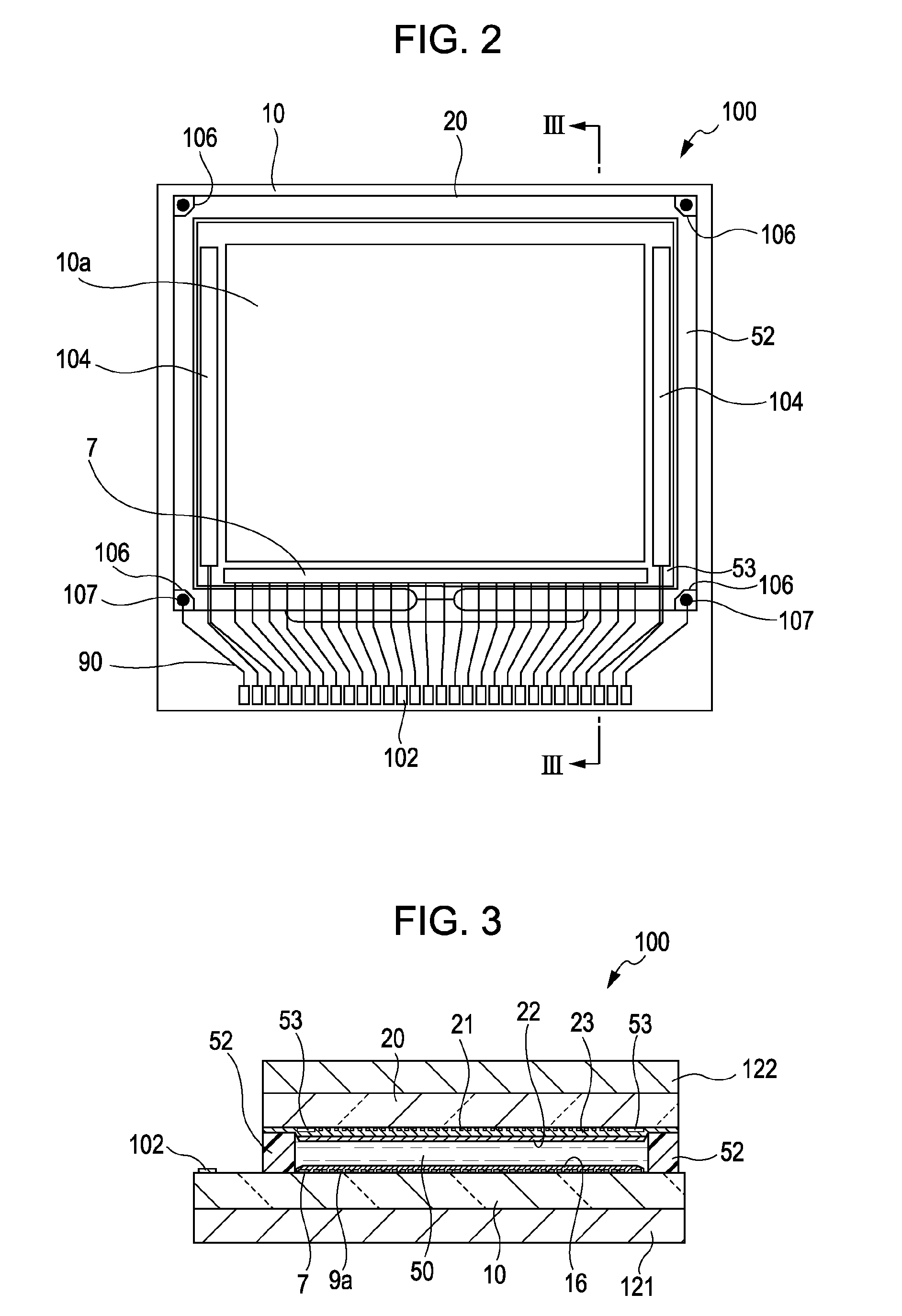
[0056]Referring now to FIG. 1 to FIG. 6, a first embodiment of the electro-optic apparatus in the invention will be described. The scales of the respective layers and members are different from the actual scale throughout the drawings in order to make these layers and members recognizable in the drawings.
[0057]First of all, referring now to the drawings, a general configuration of a liquid crystal device in the first embodiment will be described. FIG. 1 is a perspective view of the liquid crystal device according to the first embodiment.
[0058]In FIG. 1, a liquid crystal device 1 includes a liquid crystal panel 100, a wiring board 200 including a plurality of signal lines electrically connected to the liquid crystal panel 100, and a drive IC chip 300 provided on the wiring board 200 and electrically connected to at least part of the plurality of signal lines, and including at least part of a drive circuit for driving the liquid crystal panel 100. The drive IC chip 300 includes, for e...
first modification
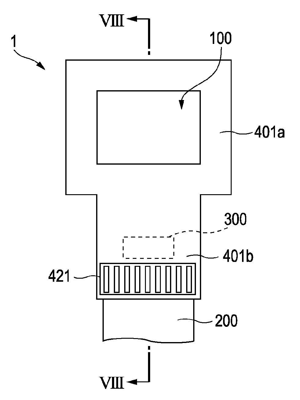
[0079]Referring now to FIG. 7 and FIG. 8, a first modification of the electro-optic apparatus according to the first embodiment will be described. FIG. 7 is a plan view of a liquid crystal device according to the first modification when viewed from the side of the opposed substrate, which is similar to FIG. 4, and FIG. 8 is a cross-sectional view taken along the line VIII-VIII in FIG. 7.
[0080]As shown in FIG. 7 and FIG. 8, a radiation fin 421 is arranged on the heat radiating portion 401b. Typically, the radiation fin 421 and the heat radiating portion 401b are bonded to each other by the mold agent or the like. The radiation fin 421 is formed of metal having high coefficient of heat conductivity such as aluminum, for example. The material to form the radiation fin 421 and the material to from the frame 401 may either be different or the same.
[0081]With the provision of the radiation fin 421, the surface area which contributes to the radiation is increased, and the good airflow is a...
second modification
[0083]Referring now to FIG. 9 and FIG. 10, a second modification of the electro-optic apparatus according to the first embodiment will be described. FIG. 9 is a plan view of a liquid crystal device according to the second modification when viewed from the side of the opposite substrate, which is similar to FIG. 4, and FIG. 10 is a cross-sectional view taken along the line X-X in FIG. 9.
[0084]As shown in FIG. 9 and FIG. 10, a radiation fin 422 is formed on the heat radiating portion 401b. In other words, the radiation fin 422 is formed integrally with the heat radiating portion 401b. Accordingly, the heat is easily transferred between the heat radiating portion 401b and the radiation fin 422. In addition, since the heat radiating portion 401b and the radiation fin 422 (and the body portion 401a as well) may be manufactured simultaneously, increase in number of steps in manufacture is prevented.
PUM
 Abstract
Description
Claims
Application Information
 - Generate Ideas
- Intellectual Property
- Life Sciences
- Materials
- Tech Scout
- Unparalleled Data Quality
- Higher Quality Content
- 60% Fewer Hallucinations
Browse by: Latest US Patents, China's latest patents, Technical Efficacy Thesaurus, Application Domain, Technology Topic, Popular Technical Reports.
© 2025 PatSnap. All rights reserved.Legal|Privacy policy|Modern Slavery Act Transparency Statement|Sitemap|About US| Contact US: help@patsnap.com


