
Gas turbine topping device in a system for manufacturing sulfuric acid and method of using turbine to recover energy in manufacture of sulfuric acid

Inactive Publication Date: 2009-03-26
WOJAK BOGDAN
View PDF9 Cites 10 Cited by
  • Summary
  • Abstract
  • Description
  • Claims
  • Application Information

AI Technical Summary

Benefits of technology

[0018]The methods are readily compatible not only with sulfuric acid plant operation, but also with sulfur load follow operational requirements, and are easily controllable during plant startup and shutdown operations.
[0021]During this improved process, the gas bubbles do not come into direct contact with the elements of the apparatus, and the walls of the reaction chamber are not heated above the temperature of the melt; furthermore, the temperature of the medium at the bubbling stage does not exceed 700-800° C., which thereby makes it possible to use common (non-refractory) construction materials; thus, it allows pressurizing the bubbling apparatus without any serious vulnerability as would be associated with pressurizing of a refractory-lined sulfur burner.
[0025]Carrying out the stage of sulfur evaporation and / or the stage of sulfur vapor oxidation under pressure, either successively or concurrently, makes it possible to convert the high energy of the combustion gases to mechanical energy through the turbine expander.
[0026]This invention provides also a method for full utilization of the full capability of existing gas turbine expanders through incorporation of pressure-exchange devices, where cooling of the sulphur combustion gases at temperatures above the tolerance of available gas turbines is accomplished by compressing another gas in an ejector. The ejector, as opposed to the turbines, can operate at very high temperatures because of its inherently simple construction which results in very low mechanical stress and high reliability.

Problems solved by technology

The sulfur is evaporated by the heat of the sulfur oxidation reaction; however, because the “flame” is submerged in liquid sulfur, the evaporation of the liquid sulfur limits the temperature of the surrounding liquid to its boiling point.

Method used


Image

  • Gas turbine topping device in a system for manufacturing sulfuric acid and method of using turbine to recover energy in manufacture of sulfuric acid
  • Gas turbine topping device in a system for manufacturing sulfuric acid and method of using turbine to recover energy in manufacture of sulfuric acid
  • Gas turbine topping device in a system for manufacturing sulfuric acid and method of using turbine to recover energy in manufacture of sulfuric acid

Examples


Embodiment Construction

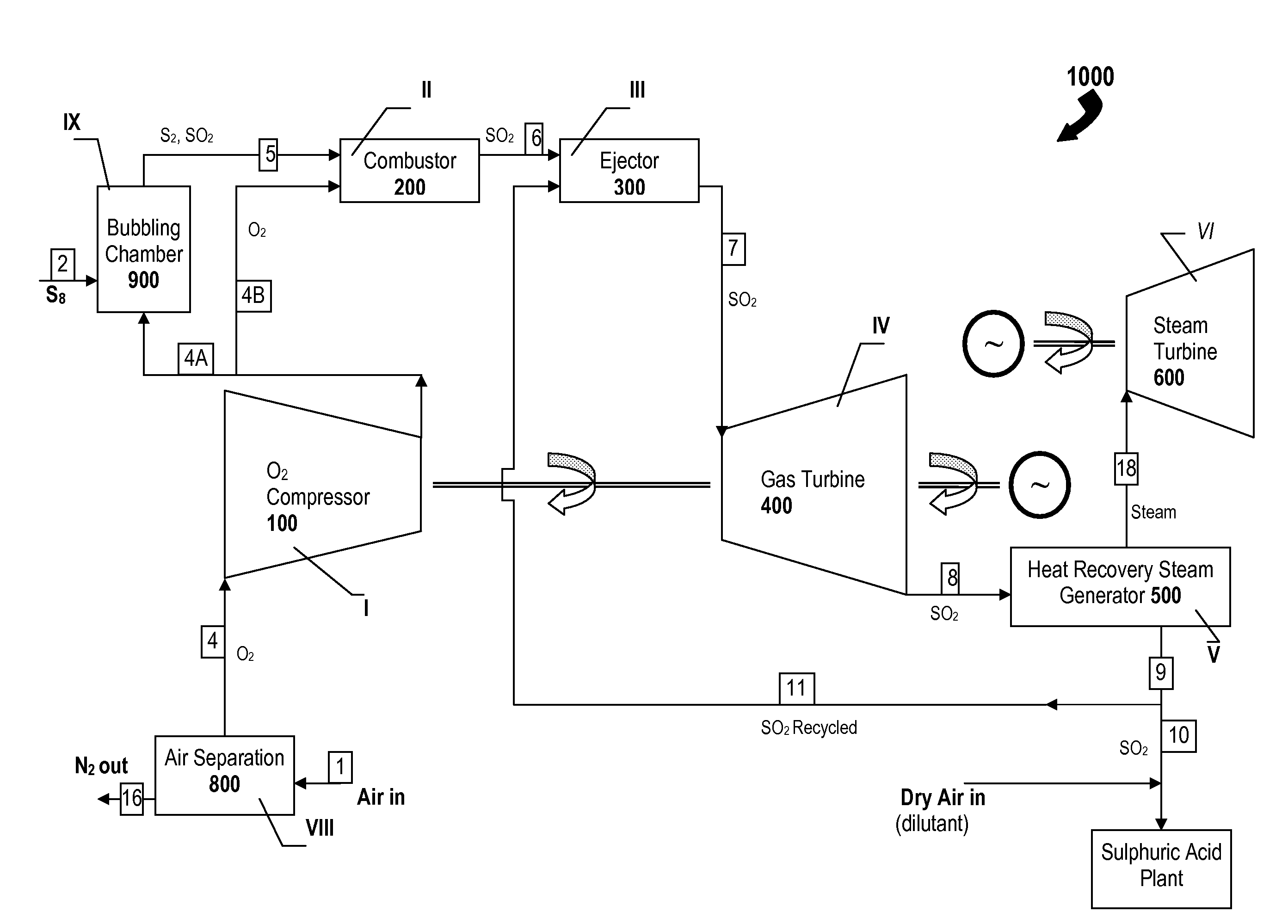
[0039]Referring to FIG. 3, there is shown a simplified example of a system 1000 adapted for combusting an adequate volume of sulfur in an oxygen-containing gas such as dry air or enriched-air in relation to a required production volume of sulfuric acid in a sulfuric acid plant and for subsequently expending all (or substantially all) of the product of the combustion reactions, in a gas turbine configured as a “topping” device that precedes a steam-raising system to thereby recover energy from the sulfur combustion, in accordance with one aspect of the present invention. The combined cycle system 1000 comprises seven main stages (I, II, III, IV, V, VI, and IX) each having at least one unit to assist in the process of burning sulfur in dry air to produce sulfur dioxide and generate electric power. As is illustrated in the first main embodiment of the present invention, the Brayton-cycle of the system 1000 comprises a compressor 100 at stage I, an ejector 200 at stage II, a combustor 3...


PUM


Abstract

A gas turbine topping device, which is disposed upstream of a steam-raising section, is used for generating power in the manufacture of sulphuric acid. A sulfur-burning combustor generates hot sulfur dioxide while a pressure-exchanging ejector mixes the hot combustion gases with a cooler gas (e.g. pressurized air, pressurized N2 or recycled sulfur dioxide (SO2) to form a mixed working gas having a temperature below the maximum allowable temperature (metallurgical limit) of the blades of the turbine. The turbine drives an oxygen compressor which supplies oxygen to a bubbling chamber which also receives S8 to produce sulfur vapor for combustion. By using stoichiometric quantities, sulfur dioxide is delivered in requisite quantities to a sulfuric acid plant without any harmful emissions. Useful amounts of electrical power can thus be generated by the gas turbine topping device as well as the downstream steam turbine by harnessing the enormous amount of waste heat involved in the manufacture of sulfuric acid.

Description

CROSS-REFERENCE TO RELATED APPLICATIONS[0001]This application claims priority under 35 USC 119(e) from U.S. Provisional Patent Application 60 / 974,965 entitled “Utilization of Sulphur Species for Power Generation” filed on Sep. 25, 2007, the contents of which are hereby incorporated by reference in their entirety to the full extent permitted by law.TECHNICAL FIELD[0002]The present invention relates generally to a method for increasing energy recovery in sulfuric acid manufacture and, in particular, to a method of utilizing the heat produced by sulfur burning directly in a gas turbine expander as a “topping” device preceding a steam-raising system.BACKGROUND[0003]Sulfuric acid plants produce a prodigious amount of high-level waste heat but nearly all of the high-level waste heat is utilized in the production of electricity through a steam turbo / generator.[0004]An alternative to generating power in steam turbines is to expand the hot combustion product gases directly to produce work in...

Claims


Application Information

Patent Timeline
IPC IPC(8): F02C6/18F02C3/20C01B32/40C01B32/50
CPCC01B17/54C01B17/74F02C6/10F02C6/18Y02E20/12C01B17/0473Y02P20/129Y10T137/0318Y02A50/20Y02P20/10
Inventor WOJAK, BOGDAN
Owner WOJAK BOGDAN
Learn More