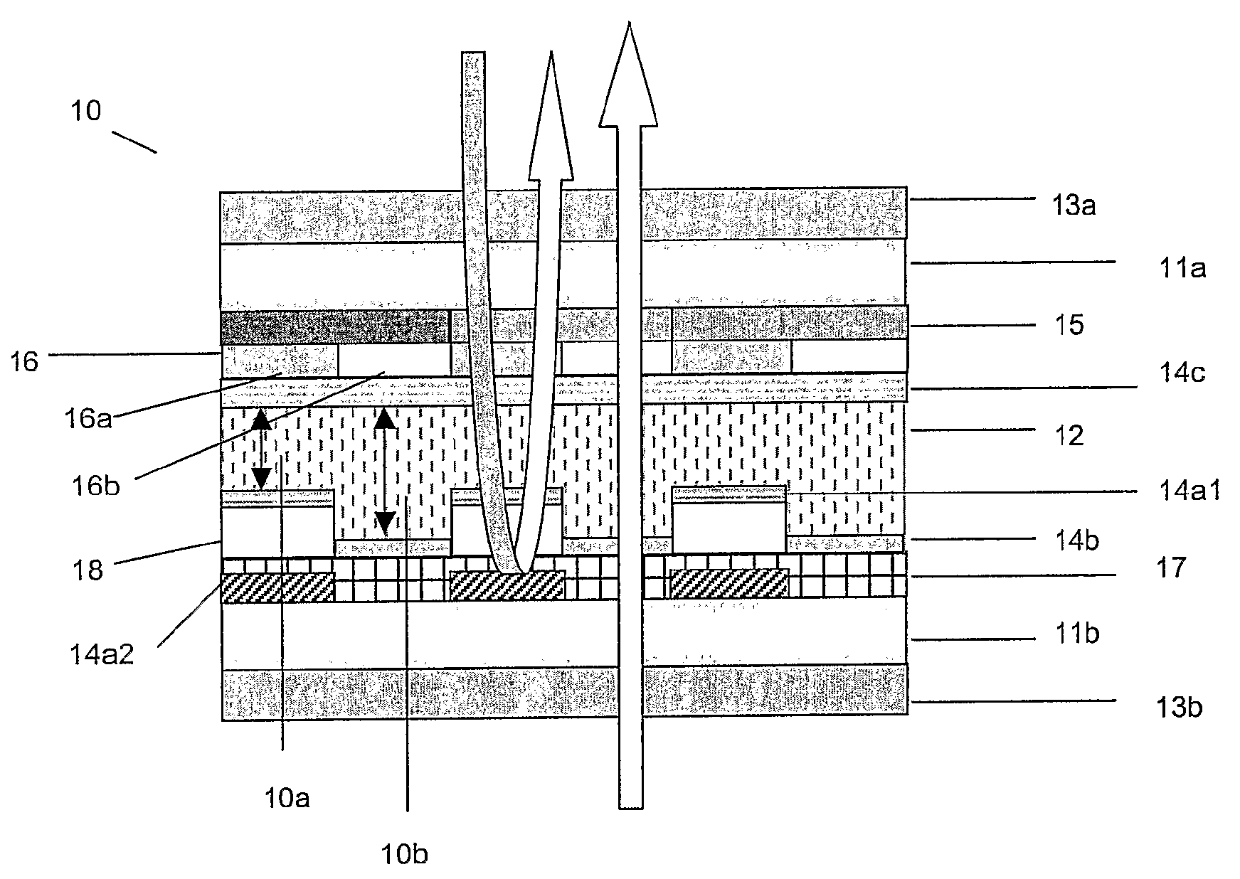
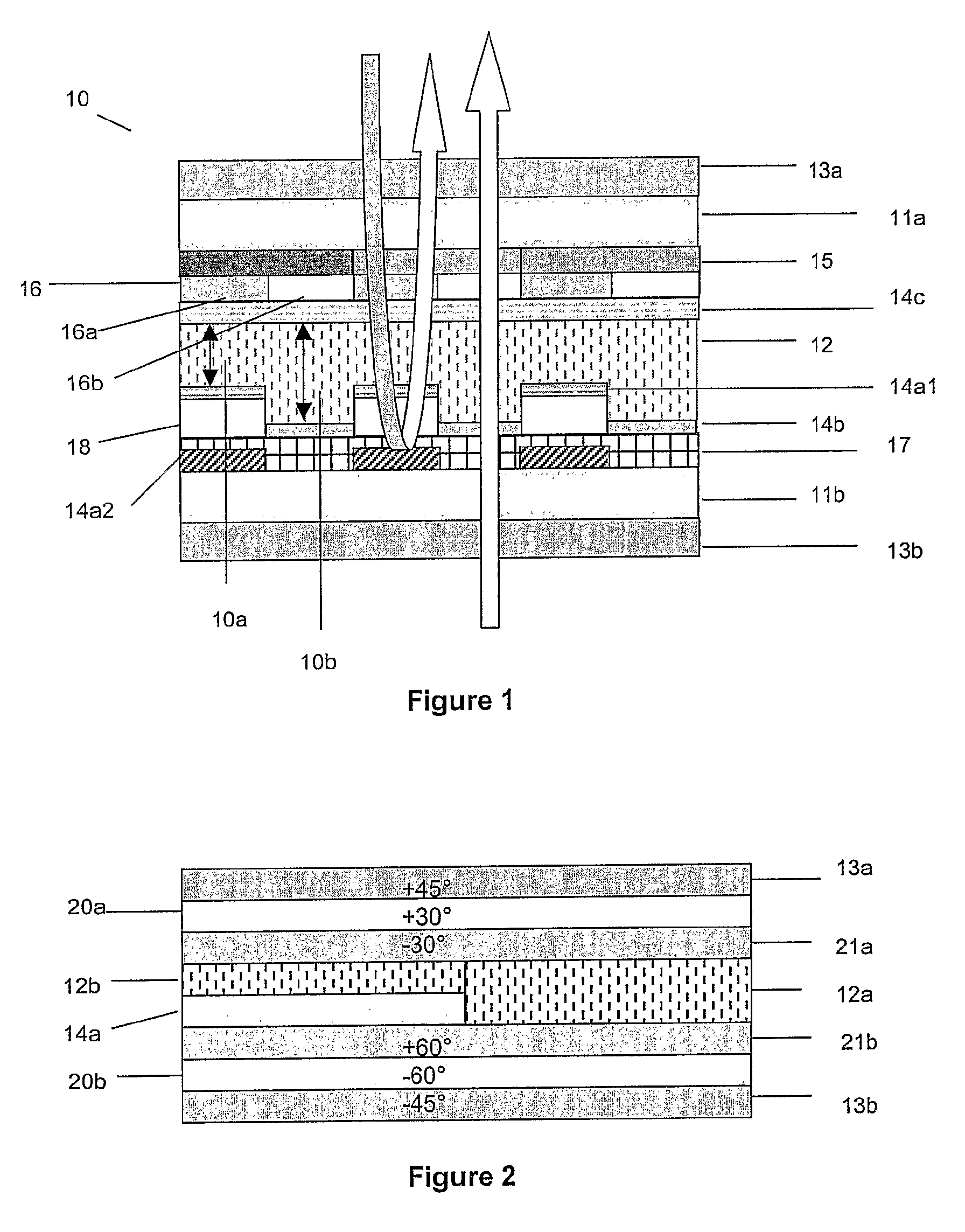
Transflective vertically aligned liquid crystal display with in-cell patterned quarter-wave retarder
a technology of liquid crystal display and quarter-wave retarder, which is applied in non-linear optics, instruments, optics, etc., can solve the problems of reducing the brightness of the display, less effective 90° twisted mode, and less efficient conversion
- Summary
- Abstract
- Description
- Claims
- Application Information
AI Technical Summary
Problems solved by technology
Method used
Image
Examples
example 1
Preparation of a Patterned QWF
[0160]The following polymerisable LC mixture is formulated
(13)14.4%(24)18.0%(35)17.0%(46)17.0%(57)32.0%Irgacure 651 1.0%Fluorad FC171 0.6%(1)(2)(3)(4)(5)
[0161]Compounds (1) to (5) are described in prior art. Irgacure 651 is a commercially available photoinitiator (from Ciba AG, Basel, Switzerland). Fluorad FC 171 is a commercially available non-ionic fluorocarbon surfactant (from 3M).
[0162]The mixture is dissolved to create a 50 wt % solution in xylene. This solution is filtered (0.2 μm PTFE membrane) and spin coated onto a glass / rubbed polyimide slide (low pretilt polyimide JSR AL1054 from Japan Synthetic Rubber). The coated film is exposed to 20 mWcm−2 313 nm radiation in air through a grey-scale (0:50:100% T) mask.
[0163]Subsequently, the film is photopolymerised using 20 mWcm−2 UV-A radiation, for 60 seconds in an N2-atmosphere, to give a patterned film having a pattern of regions with different retardations.
examples 3-8
Transflective VA Display with a Patterned Incell QWF
[0169]In the displays of examples 3-8, the viewing angle is dramatically increased in the transmissive mode by virtue of the fact that circularly polarised light is no longer required. This also allows for the use of viewing angle enhancement films, to expand it still further.
example 3
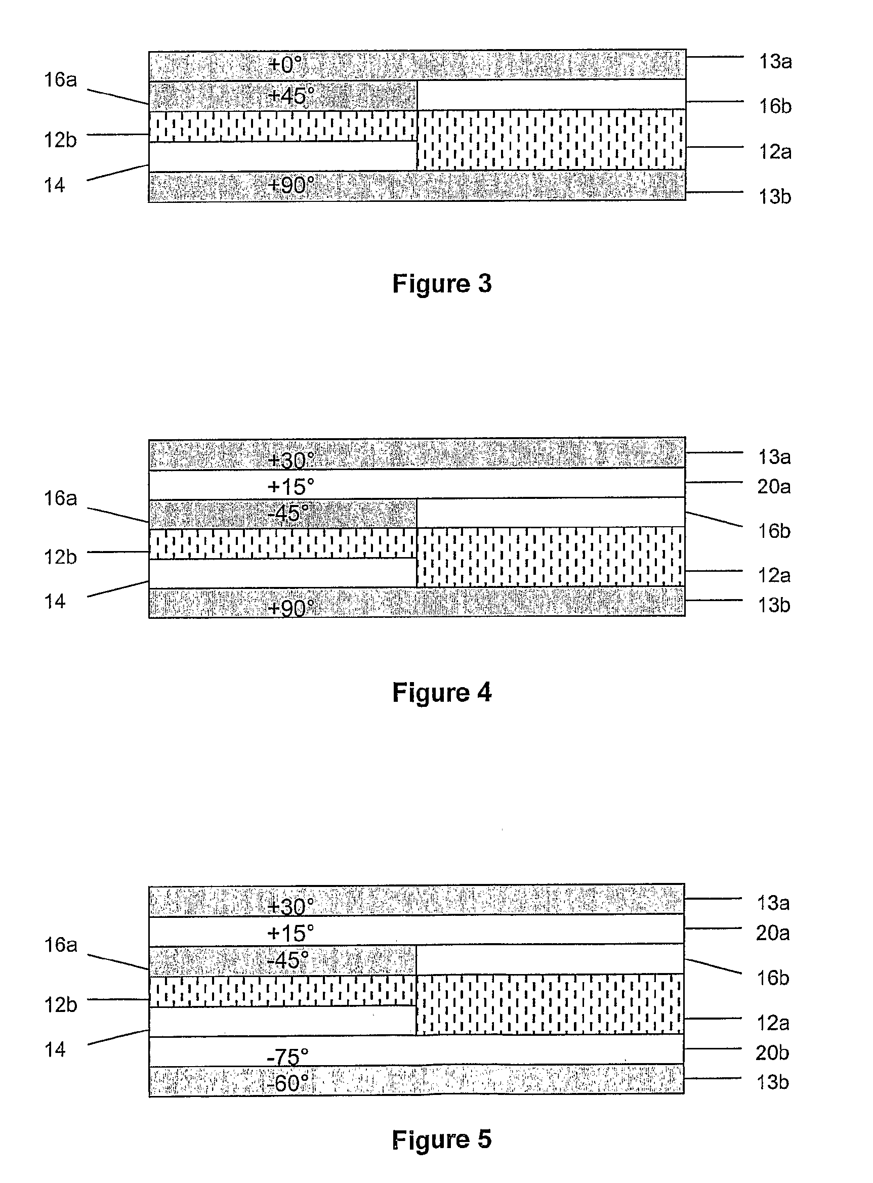
[0170]The optical performance of a pixelated transflective VA LCD according to the present invention with a stack of optical layers as shown in FIG. 3 is calculated.
[0171]The parameters of the components are as follows:
Front polariser direction: 0°Back polariser direction:+90°Retardation of LC240 nm(reflective subpixel):Retardation of LC480 nm(transmissive subpixel):Optical axis of incell QWF+45°(reflective subpixel):Retardation of incell QWF:138 nm(reflective subpixel):
[0172]The patterned incell QWF can be made for example as described in Example 1.
[0173]The angular luminance of the transmissive and reflective subpixels are shown in FIG. 11A / B. The on-axis luminance is 45.2% (transmissive) and 43.4% (reflective).
[0174]The bright state chromaticity plot of the transmissive and reflective subpixels are shown in FIG. 12 A / B. The chromaticity is 9.5% (transmissive) and 10.6% (reflective).
[0175]The on-axis contrast of the transmissive and reflective subpixels are shown in FIG. 13 A / B.
PUM
| Property | Measurement | Unit |
|---|---|---|
| thickness | aaaaa | aaaaa |
| reflection wavelength | aaaaa | aaaaa |
| wavelength | aaaaa | aaaaa |
Abstract
Description
Claims
Application Information
 - R&D
- Intellectual Property
- Life Sciences
- Materials
- Tech Scout
- Unparalleled Data Quality
- Higher Quality Content
- 60% Fewer Hallucinations
Browse by: Latest US Patents, China's latest patents, Technical Efficacy Thesaurus, Application Domain, Technology Topic, Popular Technical Reports.
© 2025 PatSnap. All rights reserved.Legal|Privacy policy|Modern Slavery Act Transparency Statement|Sitemap|About US| Contact US: help@patsnap.com


