Tire Pressure Monitoring System
a technology of monitoring system and tire pressure, which is applied in the direction of phase-modulated carrier system, instruments, anti-theft devices, etc., can solve the problems of increasing the area of the board and increasing the cost, and achieve the effect of reducing the variation in the rate of data transmission and high frequency stability
- Summary
- Abstract
- Description
- Claims
- Application Information
AI Technical Summary
Benefits of technology
Problems solved by technology
Method used
Image
Examples
first embodiment
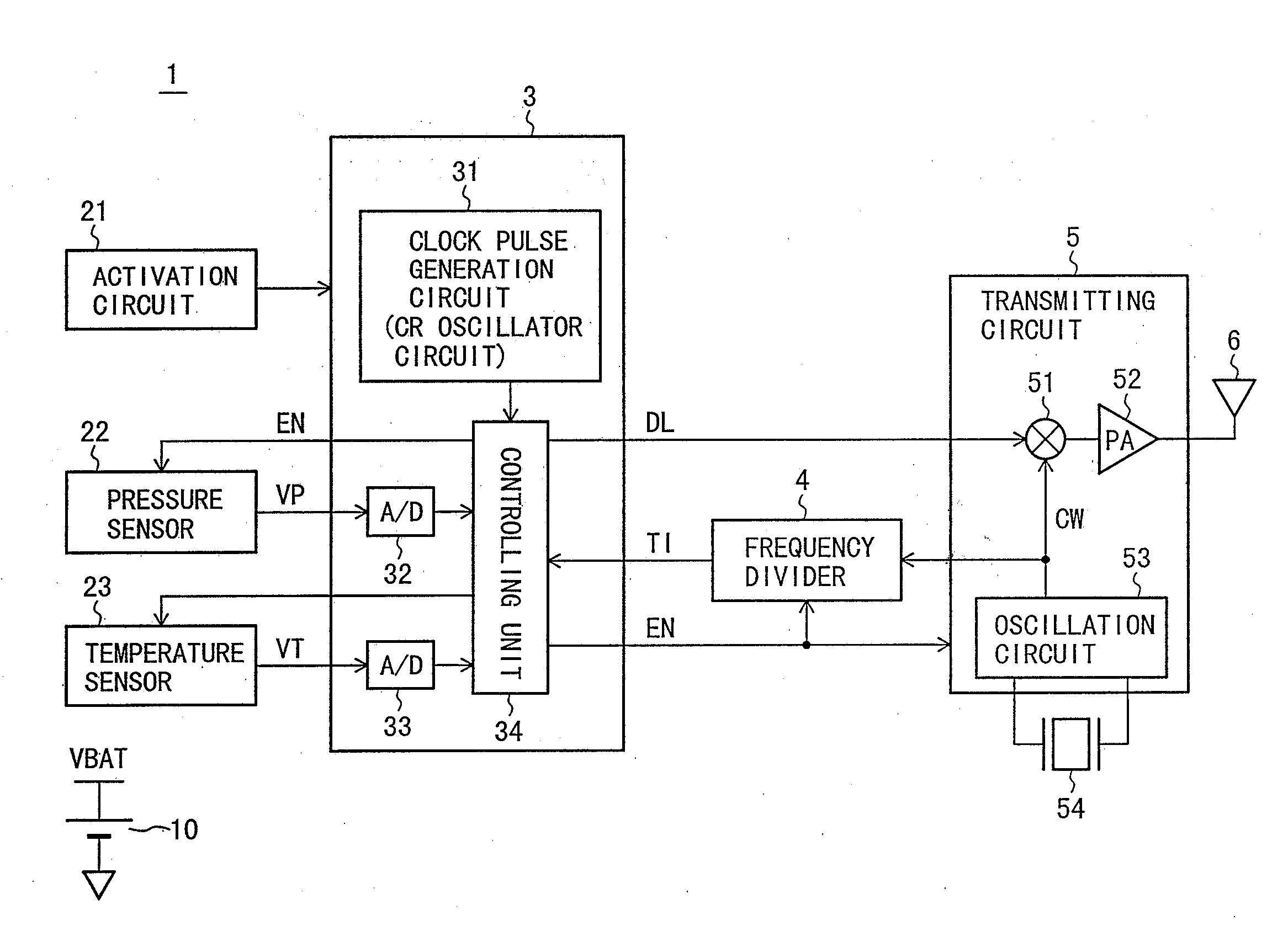
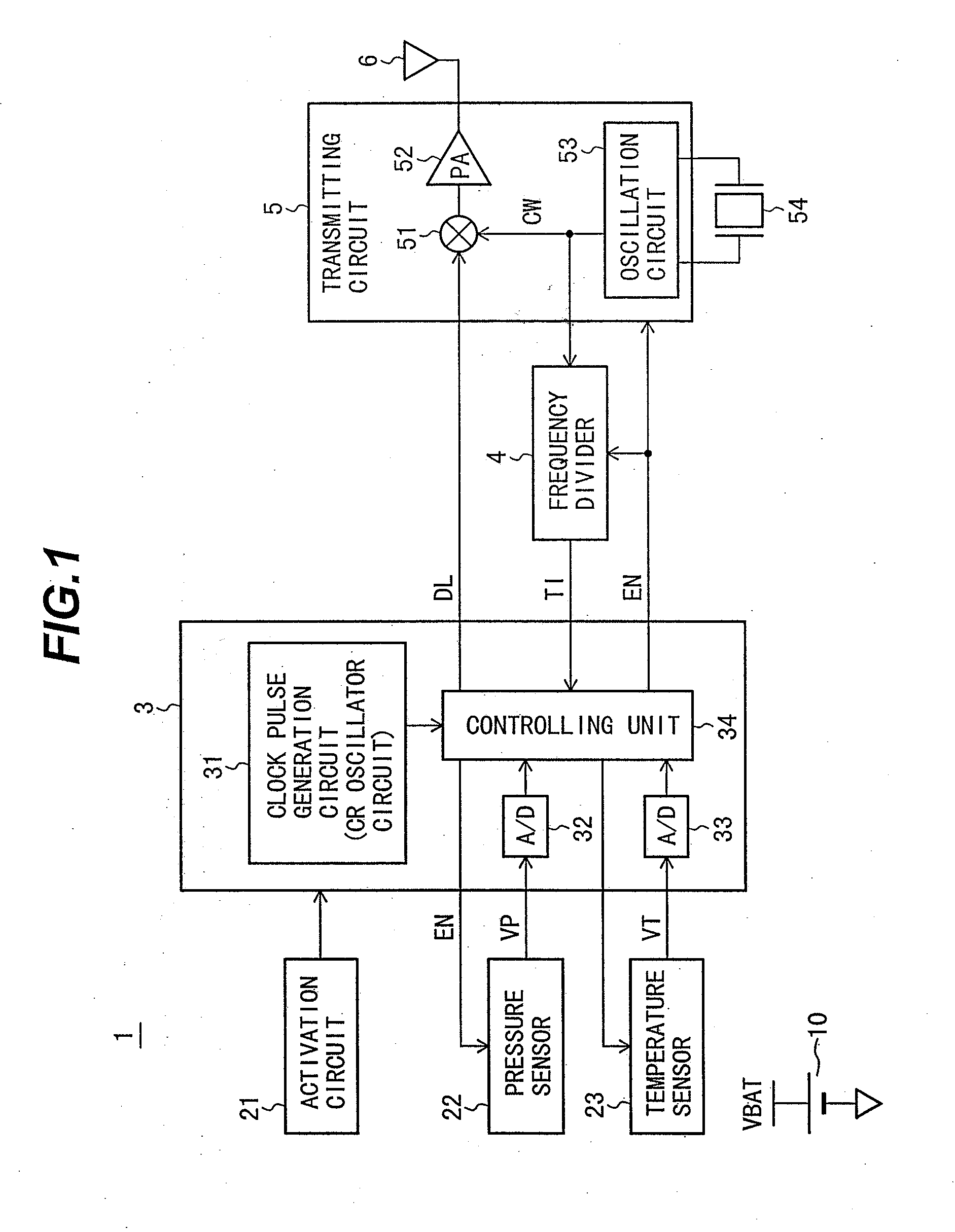
[0028]A description will be made of the configuration and operations of a tire pressure monitoring system according to a first embodiment of the present invention with reference to FIG. 1 to FIG. 7.
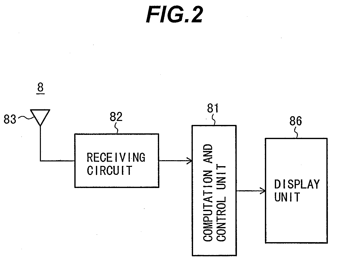
[0029]First, a description will be made of the entire construction of the system using the tire pressure monitoring apparatus according to the first embodiment of the present invention with reference to FIG. 1 to FIG. 4. FIG. 1 is a diagram showing an outline configuration of a tire pressure measuring module 1. FIG. 2 is a block diagram showing an outline configuration of an in-vehicle device 8. FIG. 3 is a diagram showing the entire configuration of the tire pressure monitoring system when viewed from a bottom surface of a vehicle.
[0030]The entire configuration of the tire pressure monitoring system will be described with reference to FIG. 3. Referring to FIG. 3, a vehicle 7 has tires 71a to 71d arranged on the front-left, front-right, rear-left, and rear-right sides thereof, respectivel...
second embodiment
[0066]A description will be made of the configuration and operations of a tire pressure monitoring system according to a second embodiment of the present invention with reference to FIG. 8. Since the basic configuration of the tire pressure monitoring system according to the second embodiment is similar to that of the tire pressure monitoring system according to the first embodiment, only different points between the first and second embodiments will be described.
[0067]That is, a frequency multiplier 55 is provided between the oscillator circuit 53 and the multiplier 51 in the second embodiment as shown in FIG. 8. In addition, the oscillator 54 provided for the transmitting circuit 5 is, for example, a crystal oscillator having an oscillation frequency of 9.84375 MHz in the second embodiment in place of the surface acoustic wave oscillator according to the first embodiment. The frequency multiplier 55 multiplies the oscillation frequency by 32 to obtain a signal having a frequency o...
third embodiment
[0070]A description will be made of the configuration and operations of a tire pressure monitoring system according to a third embodiment of the present invention with reference to FIG. 9. Since the basic configuration of the tire pressure monitoring system according to the third embodiment is similar to that of the tire pressure monitoring system according to the first embodiment, only different points between the first and third embodiments will be described.
[0071]That is, frequency shift keying (FSK) modulation is used in a transmitting circuit 50 in the third embodiment in place of the amplitude shift keying modulation used in the first embodiment, as shown in FIG. 9. Specifically, the frequency of a carrier wave oscillated by an oscillator circuit 56 is switched to a frequency of, for example, 315.0 MHz or 315.1 MHz by means of a signal output to the data signal line DL and indicating “0” or “1”.
[0072]In this case, the frequency of a timing signal generated by the frequency div...
PUM
| Property | Measurement | Unit |
|---|---|---|
| pressure | aaaaa | aaaaa |
| frequencies | aaaaa | aaaaa |
| frequency | aaaaa | aaaaa |
Abstract
Description
Claims
Application Information
 - R&D
- Intellectual Property
- Life Sciences
- Materials
- Tech Scout
- Unparalleled Data Quality
- Higher Quality Content
- 60% Fewer Hallucinations
Browse by: Latest US Patents, China's latest patents, Technical Efficacy Thesaurus, Application Domain, Technology Topic, Popular Technical Reports.
© 2025 PatSnap. All rights reserved.Legal|Privacy policy|Modern Slavery Act Transparency Statement|Sitemap|About US| Contact US: help@patsnap.com


