
Polymeric Electrolyte, Method for Production Thereof, and Electrochemical Element

a polymer electrolyte and electrolyte technology, applied in the direction of non-aqueous electrolyte cells, chemical/physical processes, non-metal conductors, etc., can solve the problems of not meeting the ionic conductivity of the polymer electrolyte, unable to achieve the high reliability originally expected for the polymer electrolyte, and unable to achieve the ionic conductivity. , to achieve the effect of high ionic conductivity and reliability

Active Publication Date: 2009-03-12
ASAHI KASEI KK
View PDF6 Cites 27 Cited by
  • Summary
  • Abstract
  • Description
  • Claims
  • Application Information

AI Technical Summary

Benefits of technology

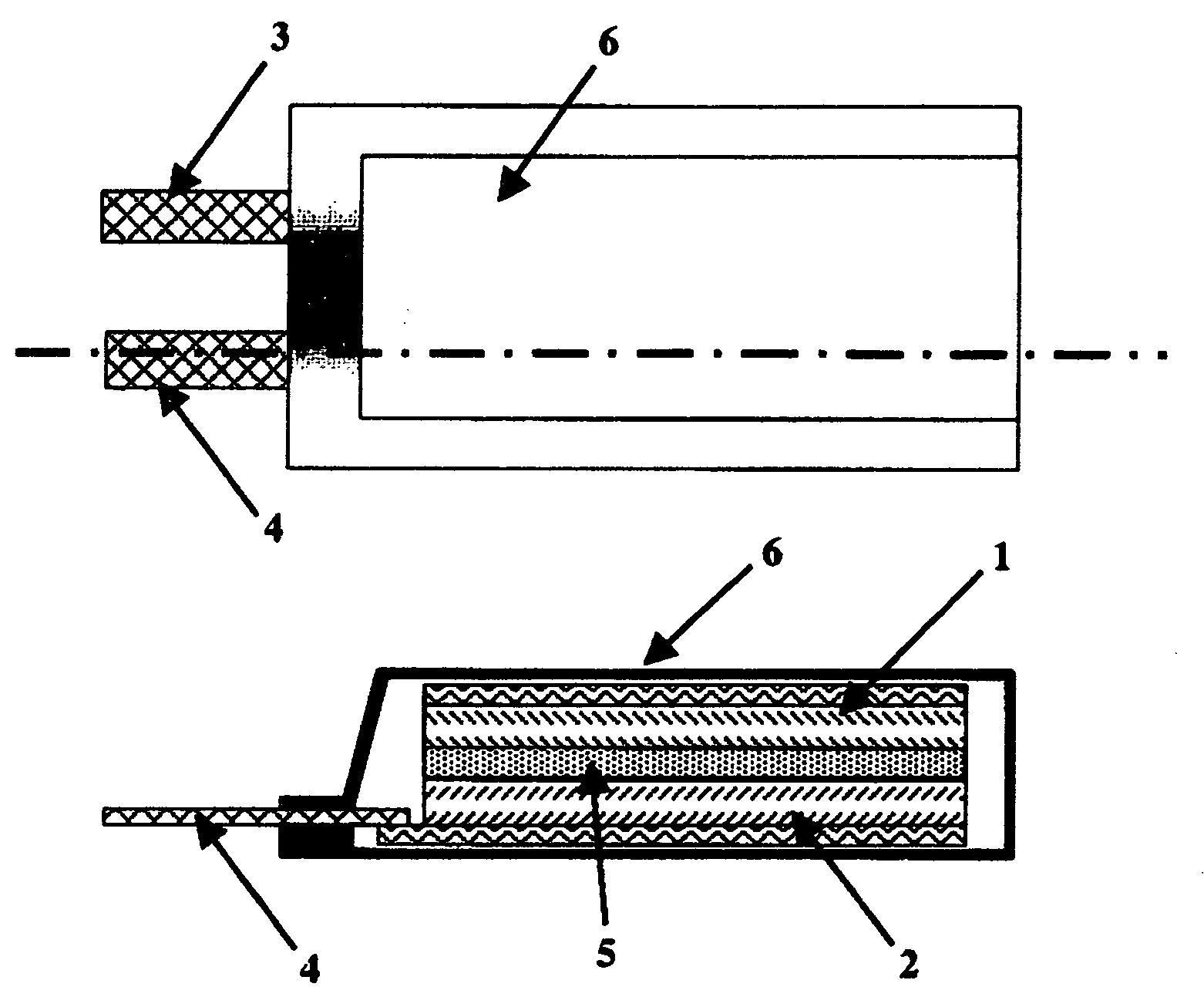
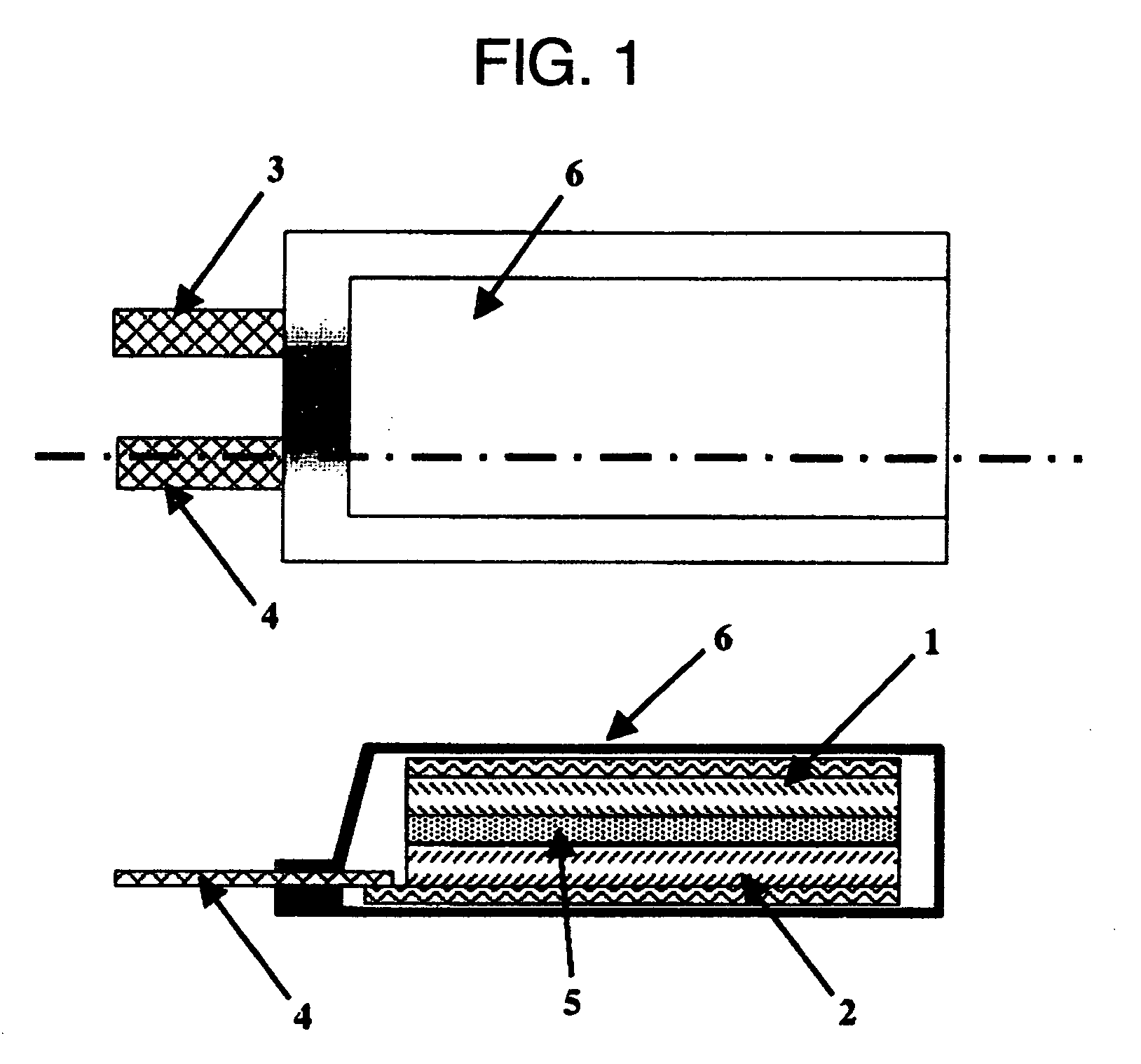
The present invention relates to a polymer electrolyte with high ionic conductivity that can be used in electrochemical devices such as batteries and capacitors. The polymer electrolyte is made of a copolymer of an ethylenically unsaturated compound and carbon monoxide. The invention solves the problem of low reliability of conventional liquid electrolytes and gel-type polymer electrolytes due to their leakage and non-aqueous electrolyte solutions. The polymer electrolyte has excellent mechanical properties, flexibility, and thin film-making ability, and can be easily produced. The invention also provides a process for producing the polymer electrolyte.

Problems solved by technology

An electrolyte solution in which an electrolyte salt is dissolved in a solvent is generally used in an electrochemical device, and when leakage liquid and further an electrolyte solution are non-aqueous electrolyte solutions, troubles such as catching fire and setting fire are caused, which make a major factor in impairing the reliability.
As described above, with respect to a polymer electrolyte, two kinds of polymer materials of an all solid-type polymer electrolyte comprising a polymer material and an electrolyte salt and a gel-type polymer electrolyte mixed with a polymer material and an electrolyte salt, and further a solvent have been proposed, but the following significant problem still remains.
That is, no material achieving practically satisfying ionic conductivity was proposed for an all solid-type polymer electrolyte.
Further, a large amount of solvent had to be mixed to obtain practical ionic conductivity in the case of a gel-type polymer electrolyte.
Therefore, from the viewpoint of reliability, reliability of each of these electrolytes is only a level better than that of an electrochemical device using a conventional liquid electrolyte, and thus high reliability originally expected for a polymer electrolyte was not achieved.
However, as described above, this gel-type polymer electrolyte contained a large amount of solvent, and high reliability originally expected for a polymer electrolyte was not obtained.
As a result, in a lithium ion secondary battery market, most of the product is occupied by the one using a liquid electrolyte and the market share of a lithium ion secondary battery using a gel-type polymer electrolyte is extremely small.
However, this system also contains a large amount of organic solvent, and the ionic conductivity is not always satisfying.
As described above, although a lithium ion secondary battery using a gel-type polymer electrolyte is put into practical use for only partial application of compact consumer batteries, major problems still remain in development of a polymer electrolyte in the present situation.

Method used


Image

  • Polymeric Electrolyte, Method for Production Thereof, and Electrochemical Element
  • Polymeric Electrolyte, Method for Production Thereof, and Electrochemical Element

Examples


reference example 1

Production of Polymer A

[0102]Into a 1 L-volume SUS autoclave with a stirrer, 800 ml of dimethyl carbonate as a polymerization solvent and 1.2 g of azobisisovaleronitrile as a polymerization initiator were charged, and subsequently a mixed gas having a pressure ratio of ethylene to carbon monoxide of 1 was charged so as to give a pressure of 4.5 MPa at room temperature. The temperature of the autoclave was raised to 60° C. while stirring. The mixture was reacted for 6 hours while adding the mixed gas so as to keep the pressure at 5 MPa. After cooling, the reactant is removed and the solid content was washed to obtain a white powder.

[0103]It was confirmed from 13C-NMR and an infrared absorption spectrum that this polymer was a product obtained by polymerizing ethylene and carbon monoxide (hereinafter, referred to as “Polymer A”), and the molar ratio of carbon monoxide was 43.2%. In addition, this Polymer A had a weight average molecular weight of 85,000.

reference example 2

Production of Polymer B

[0104]Completely the same operation as in Reference Example 1 was performed except that the pressure ratio of ethylene to carbon monoxide was changed to 2 in Reference Example 1. After cooling, the reactant was removed and the solid content was washed to obtain a white powder.

[0105]It was confirmed from 13C-NMR and an infrared absorption spectrum that this polymer was a product obtained by polymerizing ethylene and carbon monoxide (hereinafter, referred to as “Polymer B”), and the molar ratio of carbon monoxide was 21.3%. In addition, this Polymer B had a weight average molecular weight of 56,000.

reference example 3

Production of Polymer C

[0106]Completely the same operation as in Reference Example 1 was performed except that the pressure ratio of ethylene to carbon monoxide was changed to 10 in Reference Example 1. After cooling, the reactant was removed and the solid content was washed to obtain a white powder.

[0107]It was confirmed from 13C-NMR and an infrared absorption spectrum that this polymer was a product obtained by polymerizing ethylene and carbon monoxide (hereinafter, referred to as “Polymer C”), and the molar ratio of carbon monoxide was 10.9%. In addition, this Polymer C had a weight average molecular weight of 72,000.


PUM

PropertyMeasurementUnit
weight ratioaaaaaaaaaa
dielectric constantaaaaaaaaaa

Abstract

A polymeric electrolyte comprising: a polymeric material and an electrolyte salt; or a polymeric material, a solvent and an electrolyte salt, wherein a copolymer composed of 50 to 99 mol % of an ethylenically unsaturated compound and 1 to 50 mol % of carbon monoxide comprises 66.7 to 100 wt % of the polymeric material.

Description

TECHNICAL FIELD[0001]The present invention relates to a polymer electrolyte with high ionic conductivity comprising a copolymer of an ethylenically unsaturated compound and carbon monoxide, and a process for producing the same. The present invention further relates to an electrochemical device using the polymer electrolyte which has excellent liquid leakage resistance, heat resistance, and safe performance.[0002]Hereinafter, the copolymer of an ethylenically unsaturated compound and carbon monoxide includes examples of an alternative copolymer as well, and both are also collectively represented as an (alternative) copolymer depending on the context of explanation.BACKGROUND ART[0003]As portable information devices such as a laptop computer and a cellular phone have become popular, a demand for electrochemical devices such as a primary battery, a secondary battery and an electric double layer capacitor used as power supplies for the devices has rapidly increased. It is particularly r...

Claims


Application Information

Patent Timeline
Patent Type & Authority Applications(United States)
IPC IPC(8): H01G9/038H01M10/40H01M6/14C08G67/02C08K3/00C08K5/00C08L73/00H01B1/06H01B13/00H01M6/18H01M10/0525H01M10/0565H01M10/36
CPCC08G67/02C08L71/02Y02E60/13H01M2300/0091H01M2300/0082C08L73/00H01B1/122H01G9/038H01G11/56H01M6/181H01M10/0525H01M10/0565H01M2300/0025C08L2666/14C08L2666/22Y02E60/10H01G11/62H01G11/60H01M10/05H01G11/54
Inventor YOSHINO, AKIRASHOBUKAWA, HITOSHI
Owner ASAHI KASEI KK
Learn More