Pressure control valve

Inactive Publication Date: 2009-03-12
ZF FRIEDRICHSHAFEN AG
View PDF8 Cites 7 Cited by
  • Summary
  • Abstract
  • Description
  • Claims
  • Application Information

AI Technical Summary

Benefits of technology

[0016]According to an advantageous further development of the invention, the push rod is consequently configured in such a way at its end that faces the ball seat that the opening cross-section of the inlet edge can be modified depending on the axial position of the push rod, in such a way that when the target pressure is low, the cross-section is reduced in order to reduce the inlet volume flow, while when the target pressure is high, the total cross-section of the inlet edge is available in order to satisfy the high volume flow requirements of the follow-up slide valve on the one hand, and to be able to compensate for a high leakage in the working pressure on the other hand.
[0018]The transition of the inlet control edge to the tank control edge, which is carried out abruptly without the geometric expansion, can be made more gentle by way of this configuration of the push rod, whereby a startup jump in the pressure control characteristic is prevented. Further, when the volume flow requirement is low, a laminar flow can be converted into a turbulent flow in this way, which facilitates the passage of the oil at low temperatures.
[0019]As an alternative or in addition to the configuration of the push rod according to the invention, the ball seat can be designed according to the invention in such a way that its diameter on the side facing the ball is smaller than its diameter on the side facing away from the ball. The sharpened shape of the ball seat causes the conversion of a laminar flow into a turbulent flow, which facilitates the passage of the oil at low temperatures.
[0022]It is proposed within the scope of a particularly advantageous embodiment of the invention that the ball seat be made from a material whose heat expansion coefficient is considerably greater than the heat expansion coefficient of the push rod, so that at higher temperatures it features a disproportionately greater geometric expansion in comparison with the material of the push rod. This ensures that the cross-section of the inlet control edge has an ever smaller cross-section surface at increasing temperature.
[0028]This embodiment also features the advantage that the annular disk that forms the ball seat can subsequently be mounted or clipped on as insert in the pressure control handle, which makes possible a significant simplification of the production process.

Problems solved by technology

With a large quantity of shifting elements to be controlled, the result would thus be a very high oil volume requirement in the hydraulic system of the vehicle's hydraulic pump.
The transition from the inlet seat to the tank seat is carried out very abruptly, so that the leakage volume flow of the pressure regulator increases abruptly without achieving a substantial pressure increase.
This is necessary in order to keep the disturbing influences in the reducing pressure away from the working pressure to the extent possible, but leads to the disadvantage that a high leakage oil volume is produced in the low pressure range of the pressure regulator, while a high volume flow requirement of the transmission is present at the same time in this pressure range, for example, for the purpose of filling the clutch.

Method used


Image

  • Pressure control valve
  • Pressure control valve
  • Pressure control valve

Examples


Embodiment Construction

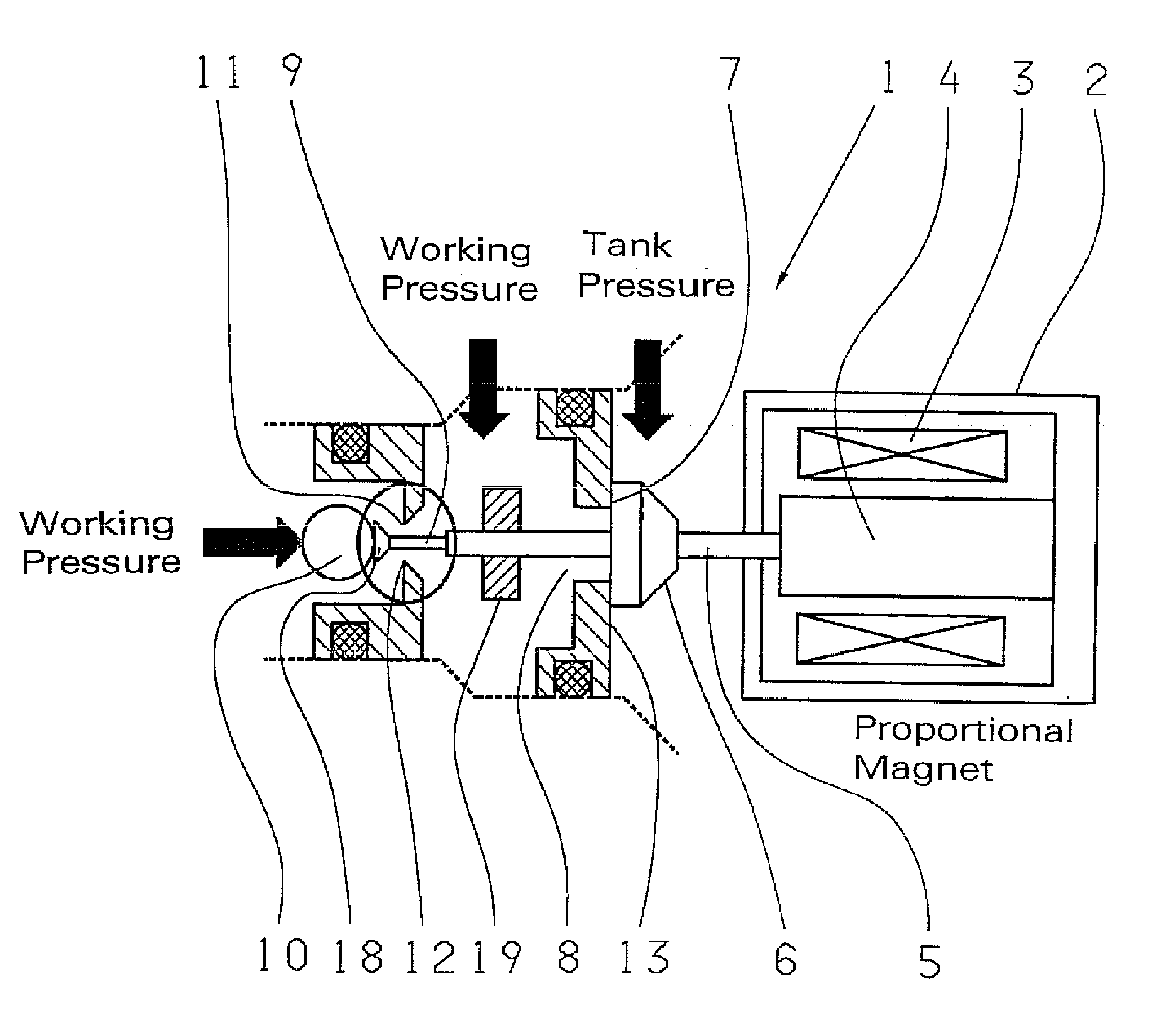
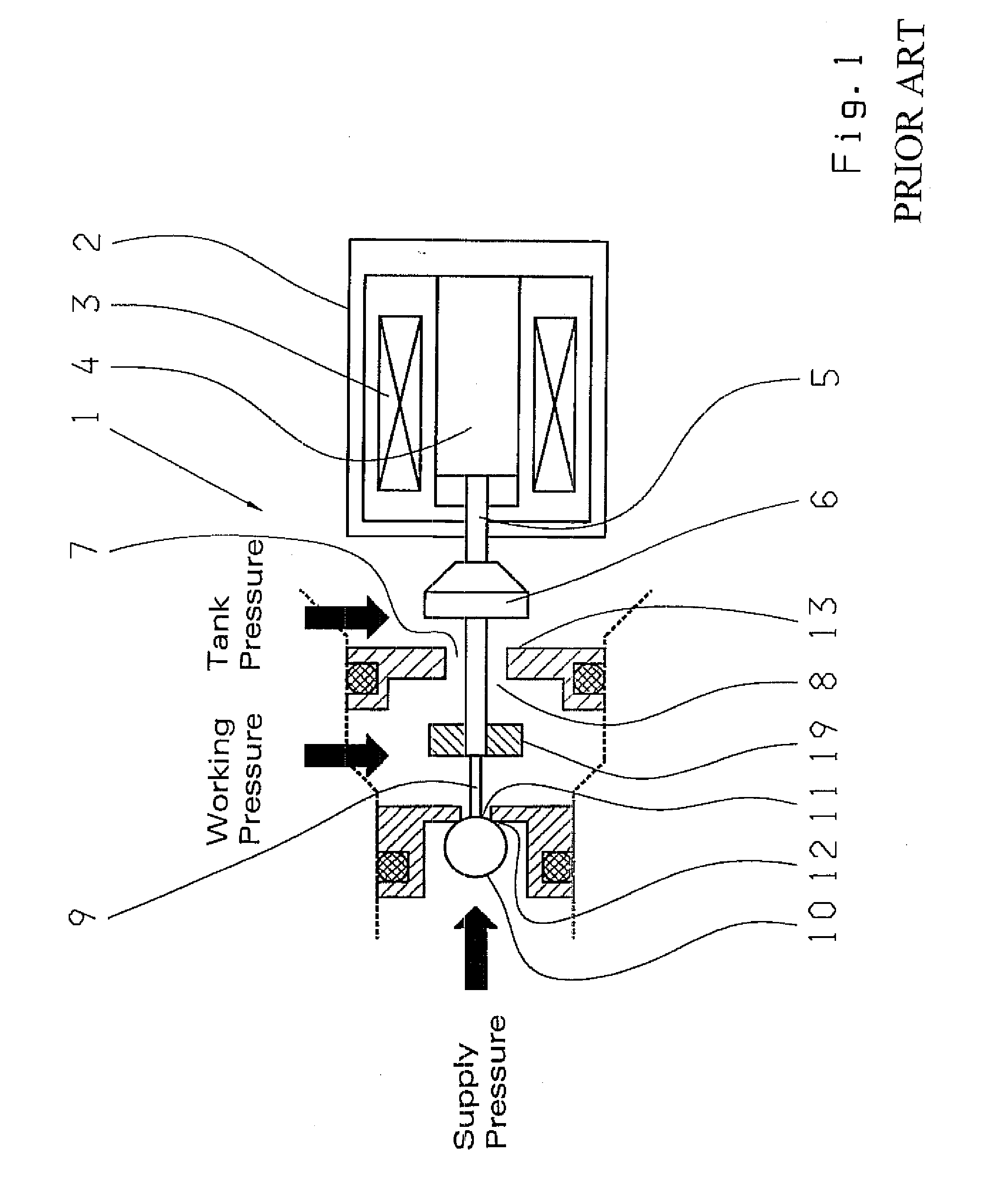
[0037]A pressure control valve 1 known from the prior art a closed-end pressure regulator in schematic representation in depressurized position (inlet control edge is closed) in FIG. 1. These proportional pressure control valves 1 are well known to persons skilled in the art so that in what follows only the parts that are necessary to understand the invention will be described.

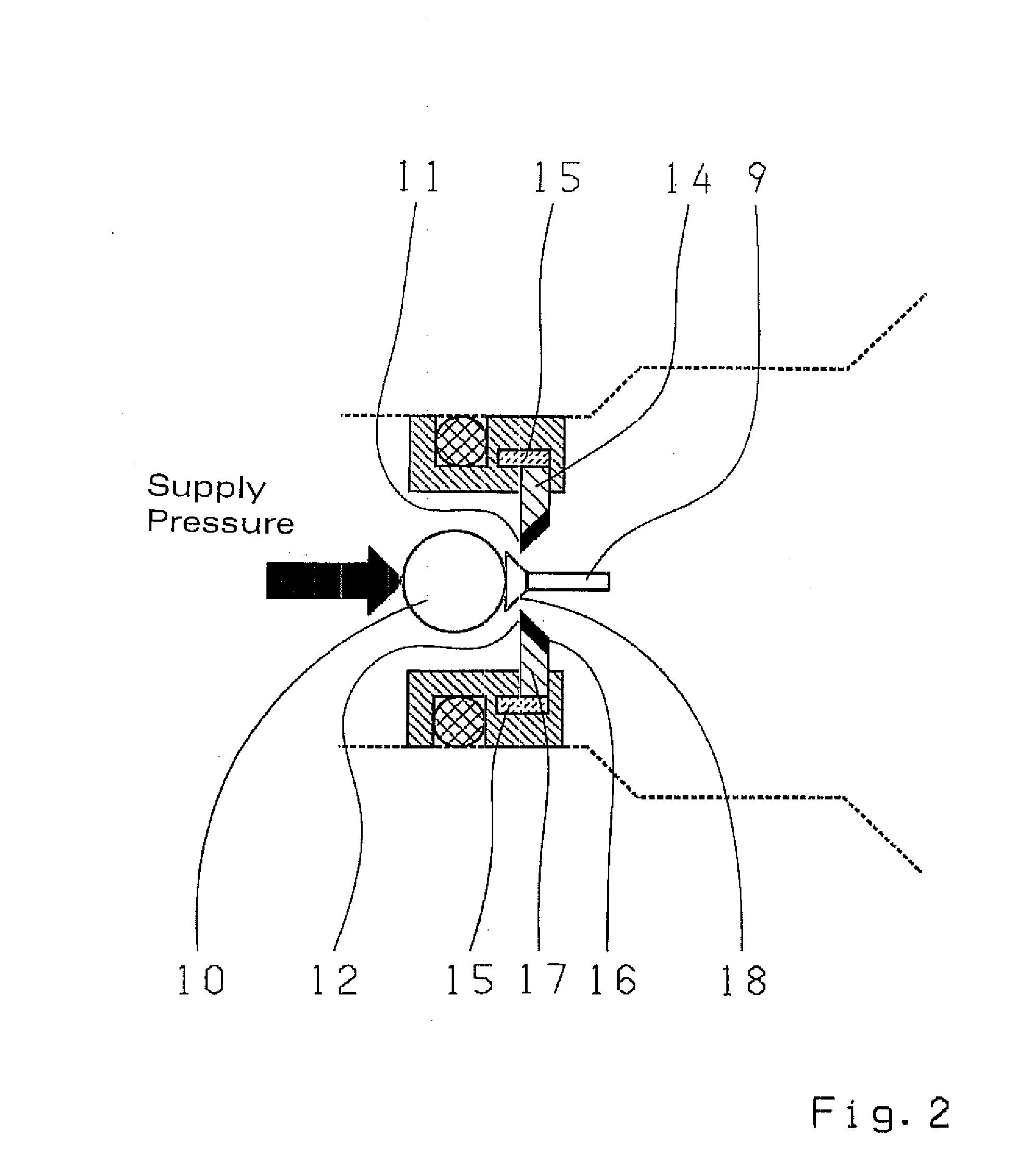
[0038]The pressure control valve 1 that serves as precontrol valve has an electromagnet 2, which customarily has a magnetic core, a magnetic coil 3 and an armature 4 that can be displaced toward the left against the force of a spring, as well as an anchor rod 5, which is displaceable by the armature 4, to bias a closing part 6 against a valve seat 7 to close an opening 8 incorporated in the valve seat 7. A push rod 9 is also provided, which is connected to the anchor rod 5 or can be designed as a single piece with the anchor rod 5, which can move a sealing element 10 designed as a ball out of a second valve se...


PUM


Abstract

A pressure control valve (1) designed as a closed-end pressure regulator is proposed, which comprises two valve seats (7, 11) arranged in a hydraulic half-bridge circuit, with an electromagnet (2) having a magnetic core, a magnetic coil (3), and a displaceable armature (4), with an anchor rod (5) displaceable by the armature (4) for a closing part (6), which can be made to strike against a first valve seat (7) of the tank edge, and with a push rod (9), which is connected to the anchor rod (5) or is designed as a single piece with the anchor rod (5), which can move a locking element (10) designed as a ball out of a ball seat (11) of the inlet control edge, in which the push rod (9) is configured in such a way at its end facing the ball seat (11) that the opening cross-section of the inlet control edge (12), that is, the ball seat (11), can be modified depending on the axial position of the push rod (9) in such a way that the cross-section is reduced when the target pressure is low, in order to reduce the inlet volume flow, while the total cross-section of the inlet edge (12) is made available when the target pressure is high and / or in which the valve seat (11) is designed in such a way that its diameter on the side facing the ball (10) is smaller than the diameter on the side facing away from the ball (10).

Description

[0001]This application claims priority from German Application Serial No. 10 2007 042 891.1 filed Sep. 8, 2007.FIELD OF THE INVENTION[0002]The invention concerns a pressure control valve.BACKGROUND OF THE INVENTION[0003]It is generally known from the prior art to utilize wet-running disk shifting elements for torque transmission in automatic transmissions of motor vehicles.[0004]Here torque transmission is effected in a friction-driven manner by pressing on the disk sets of the shifting elements, wherein for this purpose the required contact pressure on the disk set is generated via a hydraulically operated clutch piston, which is actuated via a pressure control valve (clutch valve). The pressure control valves of the shifting elements are either directly actuated or controlled via pressure limiting valves or precontrol valves connected upstream.[0005]A magnetic force, which is proportional to the control current and by way of which the purely hydraulic pressure control valves of th...

Claims


Application Information

Patent Timeline
IPC IPC(8): F15B13/044F16K31/06
CPCG05D16/2013F16K31/0634G05D16/2024Y10T137/87217
Inventor SCHMIDT, THILOMOOSMANN, MARKUSMAYR, KARLHEINZ
Owner ZF FRIEDRICHSHAFEN AG
Why Eureka
Try Eureka