
Partial load combustion cycles

Active Publication Date: 2009-03-12
VAST HLDG LLC
View PDF35 Cites 108 Cited by
  • Summary
  • Abstract
  • Description
  • Claims
  • Application Information

AI Technical Summary

Benefits of technology

[0007]The present disclosure describes a part load gas turbine cycle and method of controlling part load gas turbine operation, using diluent, including one or more of liquid water, steam, and carbon dioxide, to improve total net thermal efficiency without increasing pollutant emission levels. It further improves turbine, operational range by producing power across a greater range of part load ranges.
[0008]The part load method of operating a gas turbine comprises delivering fuel comprising fuel and oxidant fluid comprising an oxidant or oxygen, mixing and reacting these within a combustor forming products of reaction or combustion, upstream of an expander. Diluent fluid comprising a diluent may be delivered upstream of one or more of the expander outlet, upstream of the combustor outlet, and upstream of the combustor inlet, to control and deliver an energetic fluid from the combustor outlet into the inlet of the gas turbine expander. Besides oxidant or oxygen (O2) used as a reactant in the reaction or combustion process, the oxidant fluid typically includes oxidiluent fluids. E.g., oxidant fluid comprising oxygen, oxygen enriched air, or air, typically includes an oxydiluent fluid comprising one or more of nitrogen (N2), excess O2, and other minor constituents such as argon (Ar), and carbon dioxide (CO2). In the part load method, at least a portion of this cooling oxidiluent fluid may be replaced with another cooling or thermal diluent fluid comprising water, steam, and / or CO2. Controlling delivery of this thermal diluent may control the temperature within the combustion system and / or upstream of the expander outlet, while improving the system efficiency as described in this disclosure.
[0010]One of the large applications for this is in gas turbine power systems where it is desirable to maintain a relatively high turbine inlet temperature (TIT) as the power requirements are decreased. Improved efficiency during non-optimum operations such as off peak power generation is also very desirable. Controlling the thermal diluent as the system moves away from peak may be used to improve the system thermal efficiency compared to other systems using current technology.
[0011]Both the control of the TIT and efficiency can be greatly improved by controlling the thermal diluent.

Problems solved by technology

A power producer is often required to reduce their GT output power and reduce fuel use because of insufficient demand for power at various times during the day, week, and year (“off-peak”).
However, many existing gas turbine cycles, especially “Brayton” cycles, (including “simple”, Dry-Lo NOX (DLN), and Dry Low Emissions (DLE) cycles), are limited in their ability to operate at reduced power or reduced fuel consumption.
E.g., because of compressor stall limits, less efficient combustion with reduced turbine inlet temperature (TIT), and changes in combustion stoichiometry that occur during part load operation.
Declining fuel to air ratios when lowering power results in lower turbine inlet temperature and consequently substantially lower efficiency.

Method used


Image

  • Partial load combustion cycles
  • Partial load combustion cycles
  • Partial load combustion cycles

Examples


Embodiment Construction

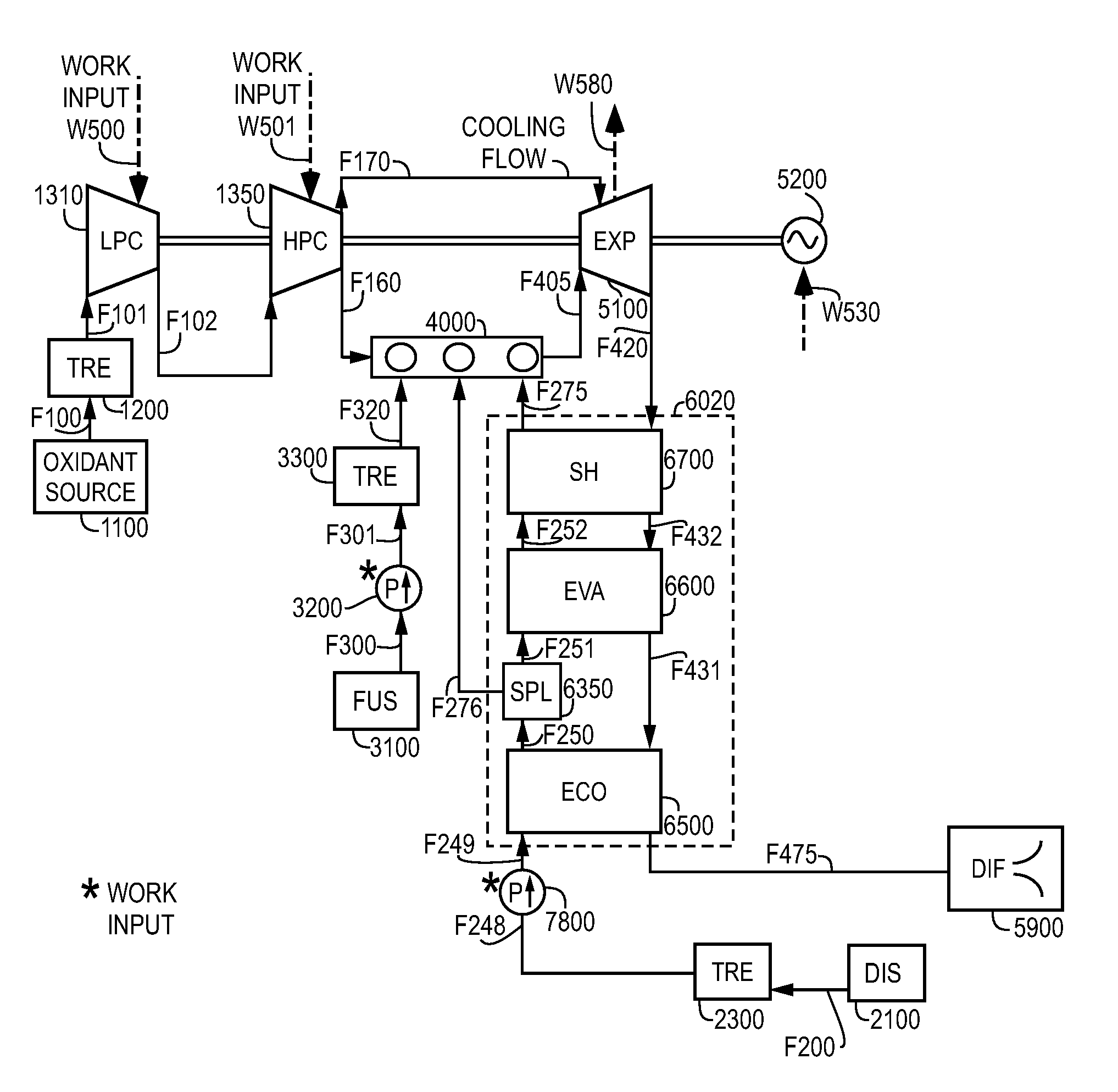
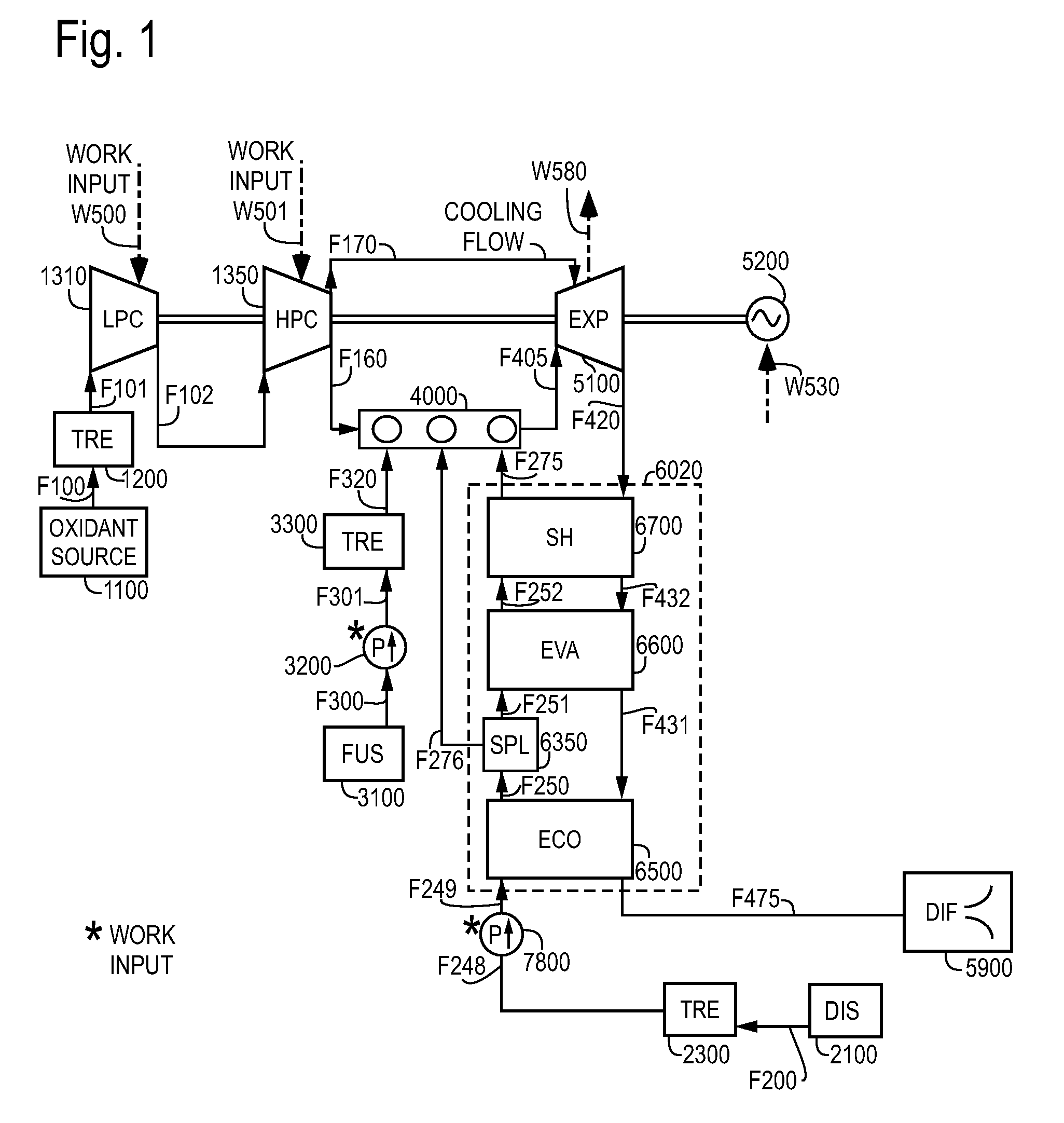
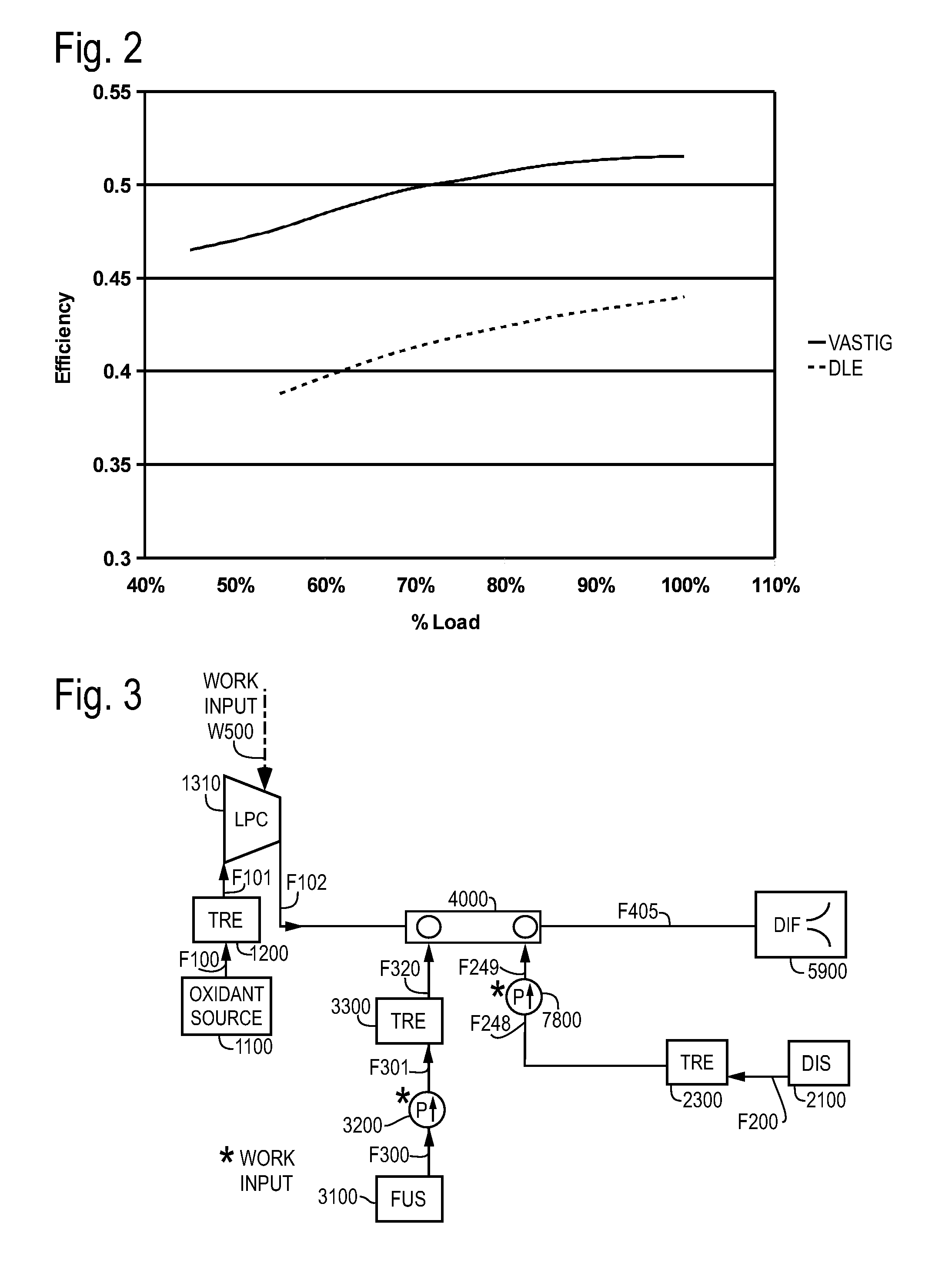
[0019]FIG. 1 shows an embodiment of the VASTIG cycle including control of thermal diluent delivery to control of the temperature in the combustion system 4000. This shows a power generation system with one or both of a low pressure compression system 1310 in fluid communication with a high pressure compression system 1350 upstream of the combustion system 4000 which is in fluid communication with an expansion system 5100 providing shaft power or work W580, which may drive an electrical power generation system 5200. Work W580 from the expansion system 5100 may drive one or more of the low pressure compression system 1310, the high pressure compression system 1350, and / or the electrical power generation system 5200 with one or more work flows W500, W501, and W530 respectively.

[0020]In some embodiments, the oxidant fluid F100 from oxidant source 1100 may be treated in an oxidant treatment system 1200 forming treated oxidant fluid F101 which may be compressed by the low pressure compres...


PUM


Abstract

The part load method controls delivery of diluent fluid, fuel fluid, and oxidant fluid in thermodynamic cycles using diluent, to increase the Turbine Inlet Temperature (TIT) and thermal efficiency in part load operation above that obtained by relevant art part load operation of Brayton cycles, fogged Brayton cycles, or cycles operating with some steam delivery, or with maximum steam delivery. The part load method may control the TIT at the design level by controlling one or both of liquid and / or gaseous fluid water over a range from full load to less than 45% load. This extends operation to lower operating loads while providing higher efficiencies and lower operating costs using water, steam and / or CO2 as diluents, than in simple cycle operation.

Description

CROSS REFERENCE TO RELATED APPLICATIONS[0001]This application claims the priority under 35 U.S.C. § 120 of U.S. patent application Ser. No. 11 / 548,281, filed 10 Oct. 2006, entitled THERMODYNAMIC CYCLES WITH THERMAL DILUENT, which is a continuation in part of U.S. patent application Ser. No. 10 / 763,057, filed 22 Jan. 2004, now U.S. Pat. No. 7,416,137, which claims priority of U.S. Provisional Patent Application Ser. No. 60 / 442,844, filed 24 Jan. 2003, and also of U.S. Provisional Patent Application Ser. No. 60 / 442,096, filed 22 Jan. 2003. This application also claims the priority under 35 U.S.C. § 119(e) of U.S. Provisional Patent Application No. 60 / 966,875, filed 30 Aug. 2007, and entitled PARTIAL LOAD COMBUSTION CYCLES. The entire contents of these applications are incorporated herein by their reference for all purposes.BACKGROUND OF THE INVENTION[0002]1. Field of the Invention[0003]The invention relates in general to methods of performing thermodynamic cycles for generating mechan...

Claims


Application Information

Patent Timeline
IPC IPC(8): F02C9/00F02C3/30
CPCB60H1/032F01K21/047F01K13/02B60H1/3223F02C3/30F02C3/305F02C7/1435
Inventor HAGEN, DAVID L.WYLIE, IANMCGUIRE, L. ALLAN
Owner VAST HLDG LLC
Learn More