
Method of driving fuel cell device

a fuel cell and device technology, applied in the direction of cell components, cell component details, electrochemical generators, etc., can solve the problems of unstable concentration of aqueous methanol solution that circulates through the anode, affecting the stability of the dmfc system,

Inactive Publication Date: 2009-03-05
KK TOSHIBA
View PDF1 Cites 5 Cited by
  • Summary
  • Abstract
  • Description
  • Claims
  • Application Information

AI Technical Summary

Problems solved by technology

If any conditions of a DMFC system, especially the stack temperature and the load current, vary when the DMFC system is activated or due to fluctuations in the ambient environment, variations in the energy consumption of an electronic device, etc., therefore, the conventional concentration control with the fuel consumption factor or the electricity generation efficiency regarded as fixed renders the concentration of the aqueous methanol solution that circulates through the anode unstable and affects the stability of the DMFC system.

Method used


Image

  • Method of driving fuel cell device
  • Method of driving fuel cell device
  • Method of driving fuel cell device

Examples


Embodiment Construction

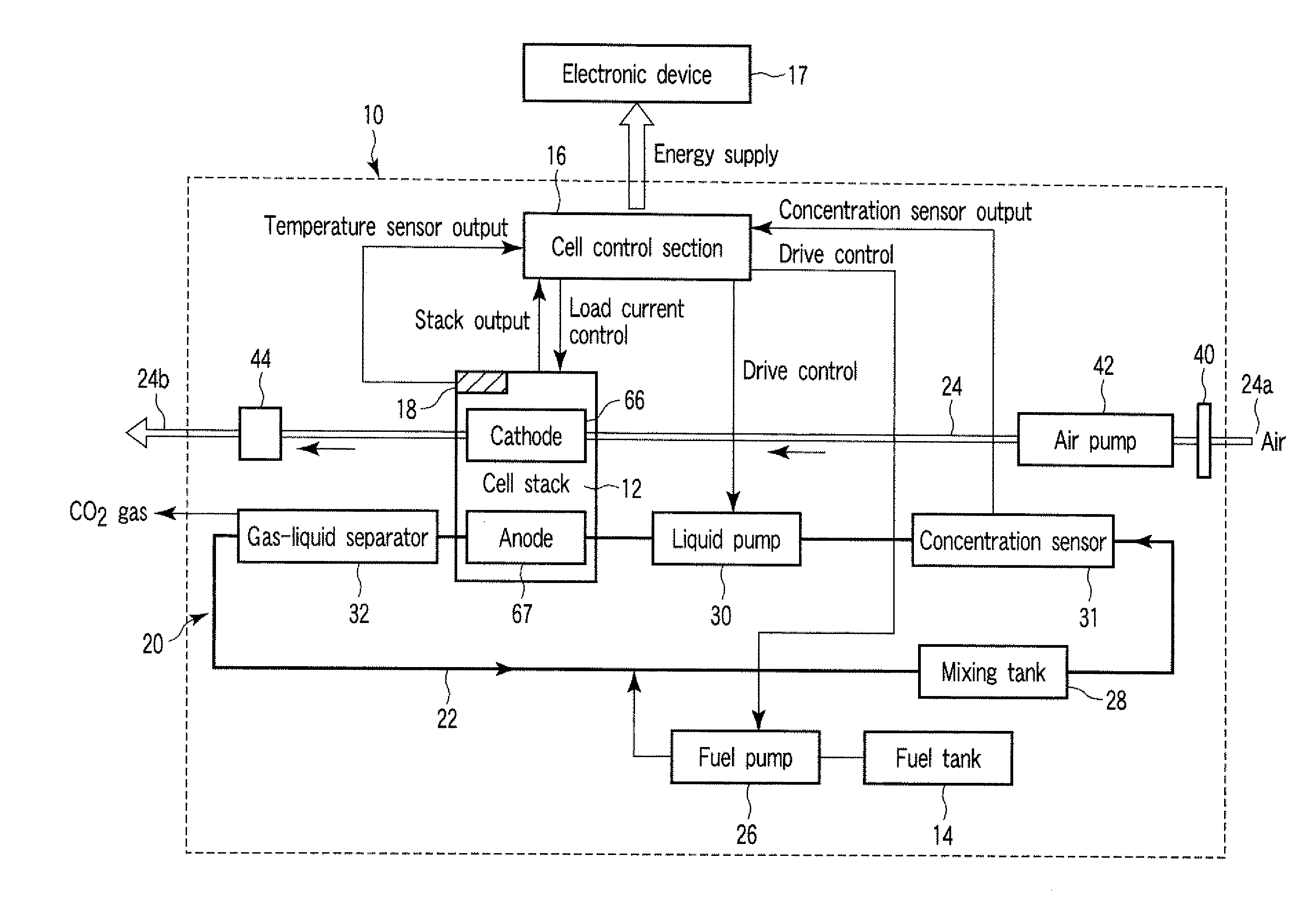
[0016]An embodiment of this invention will now be described in detail with reference to the accompanying drawings. In general, according to an embodiment of the invention, there is provide a method of driving a fuel cell device which is provided with an electromotive section which includes an anode and a cathode and generates electricity based on a chemical reaction of a fuel supplied to the anode and air supplied to the cathode, a control section which delivers an output from the electromotive section to a connected electronic device based on a load current of the electronic device, a mixing tank configured to contain the fuel supplied to the anode, a fuel channel through which the fuel supplied from the mixing tank is run via the anode side of the electromotive section, an air channel through which air is run via the cathode, a replenishment container which contains a fuel with which the mixing tank is replenished, a fuel supply section which supplies the fuel in the replenishment...


PUM


Abstract

According to one embodiment, a method of driving a fuel cell device includes calculating a fuel shortage based on a difference between the fuel concentration detected by a concentration sensor element and a predetermined desired fuel concentration, and obtaining an efficiency of electricity generation of an electromotive section based on the temperature of the electromotive section detected by a temperature sensor element and the load current measured by a control section. The method includes calculating a fuel consumption by the electromotive section for electricity generation based on the output of the electromotive section and the obtained electricity generation efficiency, and replenishing by a supply section a mixing tank with an amount of fuel equivalent to the sum of the calculated fuel shortage and the calculated fuel consumption, thereby controlling the concentration of the fuel supplied to the electromotive section.

Description

CROSS-REFERENCE TO RELATED APPLICATIONS[0001]This application is based upon and claims the benefit of priority from Japanese Patent Application No. 2007-222784, filed Aug. 29, 2007, the entire contents of which are incorporated herein by reference.BACKGROUND[0002]1. Field[0003]One embodiment of the present invention relates to a method of driving a fuel cell device for supplying a current to an electronic device or the like.[0004]2. Description of the Related Art[0005]Presently, secondary batteries, such as lithium ion batteries, are mainly used as energy sources for electronic devices, e.g., portable notebook personal computers (notebook PCs), mobile devices, etc. In recent years, small, high-output fuel cells that require no charging have been expected as new energy sources to meet the demands for increased energy consumption and prolonged use of these electronic devices with higher functions. Among various types of fuel cells, direct methanol fuel cells (DMFCs) that use a methano...

Claims


Application Information

Patent Timeline
IPC IPC(8): H01M8/04
CPCH01M8/04007H01M8/04194H01M8/04201H01M8/0432H01M8/04447Y02E60/522H01M8/04753H01M8/1011H01M2250/30Y02E60/523Y02B90/18H01M8/04589Y02B90/10Y02E60/50
Inventor NAGASAKI, TERUMASASUZUKI, TAKAHIROSEBORI, RYOICHI
Owner KK TOSHIBA
Learn More