
Heating system for plastic processing equipment having a profile gap

Inactive Publication Date: 2009-03-05
XALOY INCORPORATED
View PDF35 Cites 15 Cited by
  • Summary
  • Abstract
  • Description
  • Claims
  • Application Information

AI Technical Summary

Benefits of technology

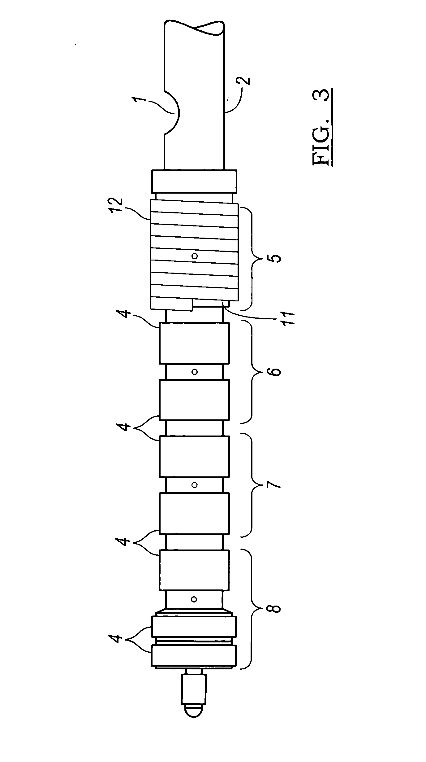
[0011]Equipping only the first zone with inductor windings and an interposed layer of thermal insulation eliminates a large share of the total heat losses to ambient. The incremental cost increase of the induction heating system is less than the cost benefit of the energy savings provided by it, thereby improving the return on investment deriving from the induction system.
[0012]When electric power to the induction windings is turned off, barrel heating ceases immediately; when induction power is turned on, the maximum heating rate is reached instantly. Induction barrel heating, therefore, reduces energy consumption, permits faster heat-up response and enables tighter temperature control during process disturbances.
[0013]Induction heating controls the barrel temperature in the first zone better during process disturbances including the cyclical addition of cold material in each machine cycle on injection molding machines, thereby reducing downstream process temperature variability.

Problems solved by technology

Consequently, band-heaters add significant thermal inertia to the system, retarding temperature control response.
As the unheated plastic feed material enters the barrel, the temperature of the barrel wall drops in the vicinity of the feed material inlet, resulting in a demand for heat in that zone.
Band-heater surface heat losses to ambient are also usually much larger in that zone where they typically operate at a higher power level, and hence are hotter, leading to exponentially higher radiation and convection losses, and lower efficiency.

Method used


Image

  • Heating system for plastic processing equipment having a profile gap
  • Heating system for plastic processing equipment having a profile gap
  • Heating system for plastic processing equipment having a profile gap

Examples


Embodiment Construction

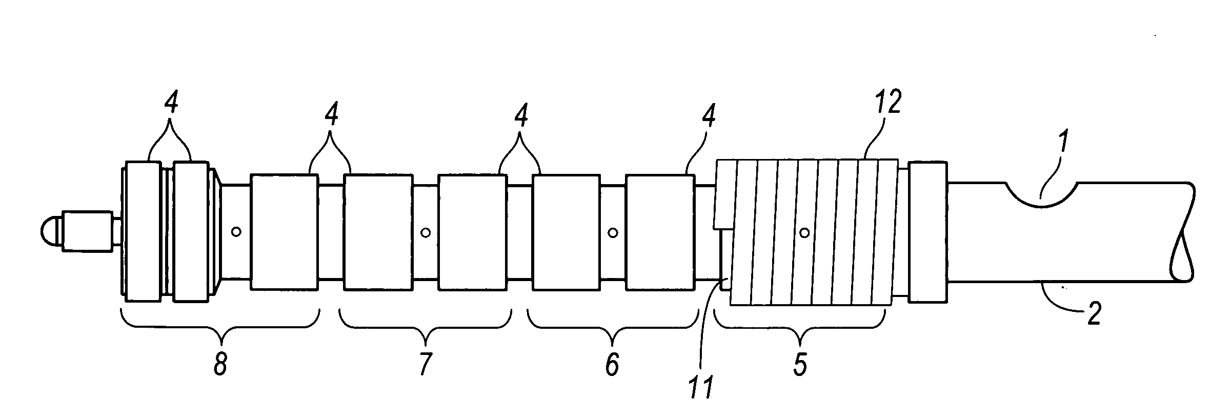
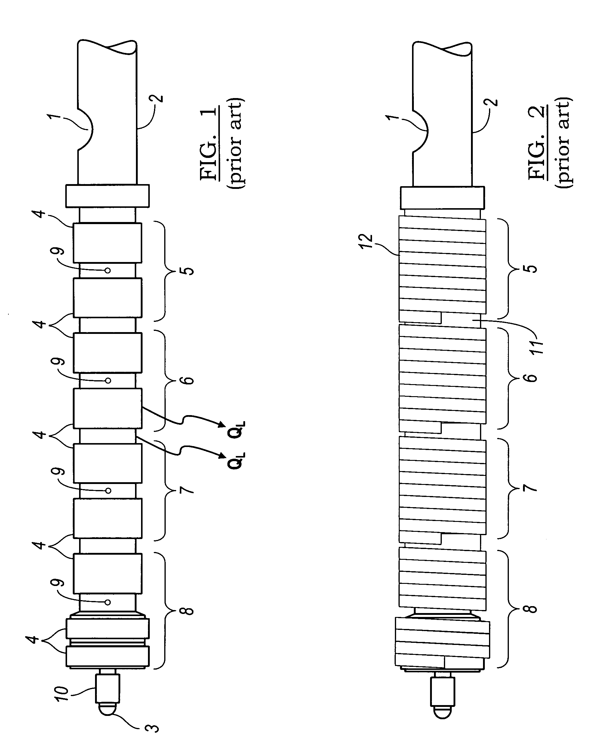
[0027]Referring to FIG. 1, solid plastic feed material, typically in the form of pellets or powder, enters the feed end 1 of a barrel 2 for injection molding and extruding plastics. Upon entering the barrel the temperature of the feed material, is low relative to a desired temperature during processing. The feed material then is sheared, mixed and metered by a screw that rotates within the barrel. The resulting molten material is then forced out of the barrel under pressure through a nozzle or die at the discharge end 3 of the barrel 2.

[0028]To help melt the plastic, the barrel 2 is also heated with external electric resistance contact heaters 4, commonly referred to as band-heaters. Furthermore, the band-heater electrical circuitry is usually arranged so that the barrel 2 can be heated in multiple controllable zones 5, 6, 7 and, 8 along the barrel's length. Usually three to six heating zones are used, each zone having one thermocouple 9 located in the barrel wall to provide measure...


PUM

PropertyMeasurementUnit
Lengthaaaaaaaaaa
Thicknessaaaaaaaaaa
Poweraaaaaaaaaa

Abstract

A system for processing plastic feed material includes a barrel having an upstream feed section and a downstream output section. A screw, supported for rotation in the barrel, cooperates with an inner surface of the barrel to form a path in which the feed material moves toward the output section. A heating system includes an induction winding encircling and extending along a portion of an outer surface of the barrel, and a gap interposed between the induction winding and the barrel and having a nonuniform thickness that varies around the periphery and corresponds to a varying wall thickness of the barrel.

Description

[0001]This application claims priority to and the benefit of U.S. Provisional Application No. 60 / 966,378, filed Aug. 27, 2007, and U.S. Provisional Application No. 60 / 967,220, filed Aug. 31, 2007, the full disclosures of which are incorporated herein by reference.BACKGROUND OF THE INVENTION[0002]1. Field of the Invention[0003]This invention relates generally to the heating of equipment used to process plastic material. More particularly, the invention relates to induction heating a metal barrel of the type used for injection molding and extrusion of plastics.[0004]2. Description of the Prior Art[0005]Solid plastic feed material enters the feed end of a barrel and then is sheared, mixed and metered by a rotating screw, which forces the material in a molten state through a nozzle or a die at the discharge end. To help melt the plastic, band-heaters, arranged on the barrel's outer surface, are heated from an electric power source.[0006]Band-heaters are typically 30 to 70 percent energy...

Claims


Application Information

Patent Timeline
IPC IPC(8): H05B6/10
CPCB29C45/74B29C47/0009H05B6/14H05B6/105B29C47/82B29B7/42B29B7/46B29B7/726B29B7/823B29B7/826B29C48/03B29C48/83B29C48/832
Inventor TAYLOR, BRUCE F.WEINRICH, ARTHUR C.KADYKOWSKI, ROBERT
Owner XALOY INCORPORATED
Learn More