
Cyanine Compound and Optical Recording Material

Inactive Publication Date: 2009-02-26
ADEKA CORP
View PDF4 Cites 12 Cited by
  • Summary
  • Abstract
  • Description
  • Claims
  • Application Information

AI Technical Summary

Benefits of technology

[0007]The present inventors conducted diligent research and, as a result, found a cyanine compound of a specific molecular structure, having absorption wavelength characteristics suitable for forming an optical recording layer of an optical recording medium for short-wavelength recording light. The inventors envisaged that the use of this compound may solve the problems.

Problems solved by technology

However, as an optical recording material used to form an optical recording layer, these compounds have problems that their absorption wavelength characteristics are not necessarily suitable or that they do not have excellent recording characteristics.

Method used


Image

  • Cyanine Compound and Optical Recording Material
  • Cyanine Compound and Optical Recording Material
  • Cyanine Compound and Optical Recording Material

Examples


examples

[0055]Hereafter, the present invention will be described in more detail in terms of Manufacturing Examples and Examples. However, the present invention will not be limited in any way by the following Examples and the like.

[0056]The following Manufacturing Examples 1 to 12 show examples of manufacture of the cyanine compounds of the present invention. Further, the following Examples 1 to 12 show examples of optical recording material and optical recording medium of the present invention using the cyanine compound of the present invention obtained in Manufacturing Examples 1 to 12. Comparative Example 1 shows an example of an optical recording material and an optical recording medium, which was prepared using a cyanine compound of a structure different from the cyanine compound of the present invention. Also, in the following Evaluation Example 1, thermal decomposition behavior was evaluated by measuring the melting and decomposition points of the cyanine compound of the present inven...

manufacturing example 4

Manufacture of a Quencher Anion (C) Salt of Cyanine Compound No. 2

[0063]To a reaction vessel were charged 0.69 mmol of tetrafluoroborate salt of cyanine compound No. 2, 0.69 mmol of a triethylamine salt of the anion represented by the chemical formula [C], and 3.6 g of pyridine, and the mixture was stirred at 60° C. for 2 hrs. and, after addition of 8 g of methanol, was allowed to cool to room temperature. The precipitated solid was collected by filtration and dried under vacuum to obtain the desired quencher anion (C) salt of compound No. 2. The compound obtained was identified by IR and 1H-NMR analyses. The analytical results are shown in [Table 2] and [Table 3]. Also, in [Table 1], the yield of the compound synthesized and results of measurement of the characteristic values [optical absorption characteristics (λmax and ε at λmax) dissolved in a solution] are shown.

manufacturing examples 6 and 7

Manufacture of Quencher Anion (D) Salts of Cyanine Compound Nos. 35 and No. 36

[0064]Except that triethylamine salt of an anion represented by the chemical formula (D) was used instead of the triethylamine salt of anion represented by the chemical formula (C), the reaction was carried out in a similar manner as in Manufacturing Example 4 to obtain the respective, desired quencher anion (D) salts of compound Nos. 35 and 36. The compounds obtained were identified by IR and 1H-NMR analyses. The analytical data are shown in [Table 2] and [Table 3]. Also, in [Table 1], yields of the compounds synthesized and results of measurement of the characteristic values [optical absorption characteristics (λmax and ε at λmax) in solution state] are shown.

TABLE 1YieldεCyanine compound(%)λmax(×104)ManufacturingTetrafluoroborate salt36460.04.37Example 1of compound No. 1ManufacturingTetrafluoroborate salt8.3475.53.86Example 2of compound No. 2ManufacturingTetrafluoroborate salt60457.54.74Example 3of comp...


PUM


Abstract

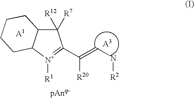
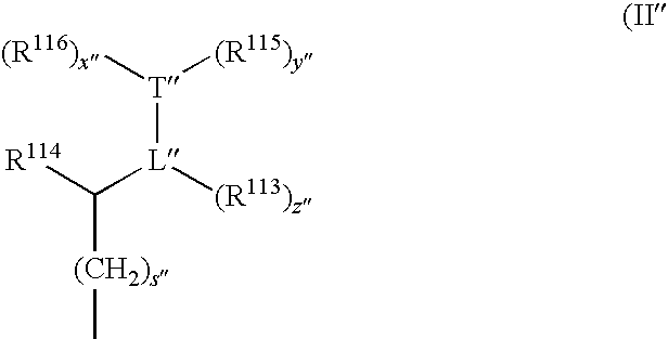
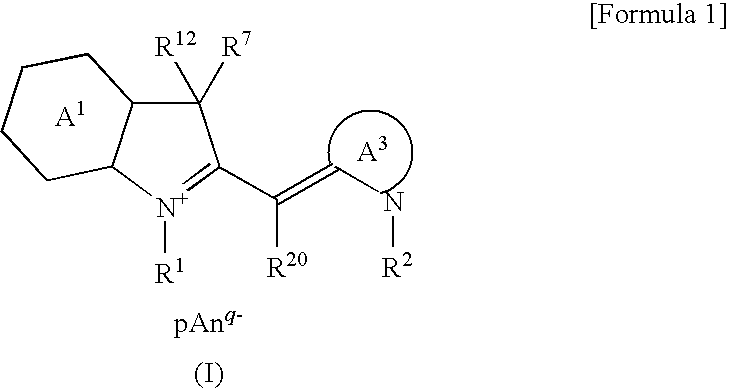
A cyanine compound is represented by formula (I):A1: benzene or naphthalene ring. A3: 5- or 6-membered ring. R1, R2: hydrogen atom and the like. R7: an alkyl group and the like. R12: a substituent by formula (II) or (II′). R20: a hydrogen atom and the like. Anq-: a q-valent anion. q: 1 or 2; p: a coefficient for neutral charge. In formula (II): bond between L and T is a double, conjugated double, or triple bond. L: carbon atom. T: carbon, oxygen, sulfur, or nitrogen atom. x, y, z: 0 or 1. s: 0-4. R13: hydrogen atom and the like. R14, R15, and R16: hydrogen atom and the like. In formula (II′), the bond between L′ and T′ is a double or conjugated double bond. L′: carbon atom. T′:carbon, oxygen, nitrogen atom. s′: 0-4. Ring containing L′ and T′: 5-membered ring, may contain a heteroatom.

Description

TECHNICAL FIELD[0001]The present invention relates to a novel cyanine compound and an optical recording material comprising the cyanine compound. The cyanine compound is useful as an optical recording agent to be comprised in an optical recording material, which is used in an optical recording layer of an optical element and the like, especially an optical recording medium, information being recorded thereon and reproduced therefrom as information patterns by means of a laser and the like. The optical recording material is especially useful for an optical recording medium, which is capable of high-density optical recording and reproduction by a laser and the like, the laser having emissions in ultraviolet and visible regions, and being of low energy.BACKGROUND ART[0002]The optical recording media are in widespread use, generally due to its superior characteristics such as large recording capacities, and noncontact recording or reproduction. In the write-once optical discs such as WO...

Claims


Application Information

Patent Timeline
IPC IPC(8): C07D215/00C07D417/02C07D209/56C07D263/52C07D235/02G11B7/246G11B7/2467G11B7/2472G11B7/249G11B7/2492G11B7/2495
CPCC07F17/02C09B23/04G11B7/2467G11B7/2495G11B7/249G11B7/2492G11B7/2472C07D209/08C07F17/00C09B23/00
Inventor YANO, TORUYANAGISAWA, SATOSHIAOYAMA, YOHEISHIGENO, KOICHI
Owner ADEKA CORP
Learn More