
Surface treated anode and lithium battery using the same

Inactive Publication Date: 2009-02-26
SAMSUNG SDI CO LTD
View PDF4 Cites 27 Cited by
  • Summary
  • Abstract
  • Description
  • Claims
  • Application Information

AI Technical Summary

Benefits of technology

[0009]Aspects of the present invention provide a surface treated anode having improved initial efficiency and cycle characteristics.
[0010]Aspects of the present invention provide a method of preparing a surface treated anode having improved initial efficiency and cycle characteristics.

Problems solved by technology

However, when lithium metals are used in lithium batteries, short circuits may occur, due to lithium dendrite formation, which can cause explosions.
However, although amorphous carbon has a high capacity, many of its charge / discharge reactions are irreversible.
Although the theoretical capacity of such graphite or carbon-based active materials (approximately 380 mAh / g) is relatively high, it is not high enough for future higher capacity lithium batteries.
However, such materials have shorter life cycles than carbon-based materials, and thus, cannot be put to practical use.
This may result in the degradation of an electronic conduction network between the active material particles, or may result in the detachment of an anode active material from an anode current collector.
Therefore, after repeated charge / discharge cycles, spaces may be generated between the active material particles, and electrical insulation may occur, thereby rapidly lowering the life cycle characteristics of these materials, and causing serious problems when using these materials in lithium batteries.
However, there may be several disadvantages in using such materials, such as, severe electrochemical irreversibility during charging and discharging.
This may be caused by increases in the defects and the specific surface area of carbon, during a compounding process.
In addition, the charge / discharge efficiency is lowered, due to weakened bonds between active material particles, which may be caused by the extreme expansion and contraction of the active materials.

Method used


Image

  • Surface treated anode and lithium battery using the same
  • Surface treated anode and lithium battery using the same
  • Surface treated anode and lithium battery using the same

Examples


example 1

[0050]7.5 g of the composite anode active material powder, 1.5 g of graphite powder, and 20 g of 5 wt % of a PVDF solution (solvent: NMP) were mixed using a mechanical stirrer, to prepare a mixture (slurry). The slurry was coated on a copper (Cu) current collector using a doctor blade to a thickness of about 200 μm. The coated slurry was dried on the Cu current collector, at room temperature, and then dried again under a vacuum, at 130° C., thereby preparing an anode plate.

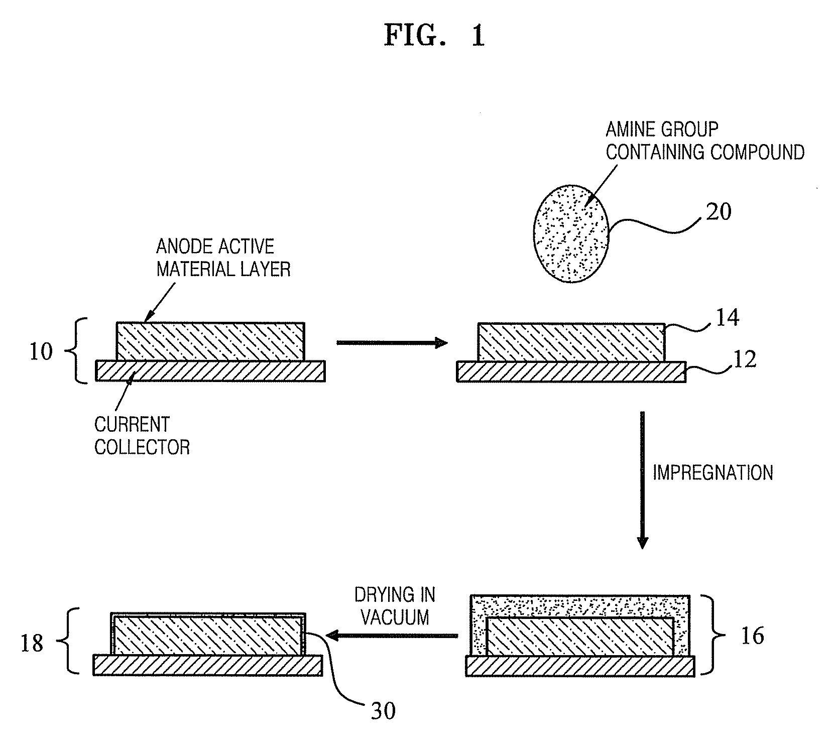
[0051]Aminopropyltriethoxy silane was added to dimethyl carbonate (DMC), and then stirred for 2 hours, to prepare a 0.5 wt % solution. 0.25 mL of the solution was applied to a 1 cm2 surface area of the anode. A vacuum was applied, such that the solution was drawn into the anode, at room temperature, and the dimethyl carbonate solvent was removed. Thereafter, drying was performed in a vacuum oven at 120° C., for 2 hours, thereby finally preparing a surface treated anode.

example 2

[0052]A surface treated anode was prepared following the same procedure as in Example 1, except that instead of aminopropyltriethoxy silane, aminopropyltrimethoxy silane was used, to form the surface treated anode.

example 3

[0053]A surface treated anode was prepared following the same procedure as in Example 1, except that a 1 wt % aminopropyltriethoxy silane solution was produced, to form the surface treated anode.


PUM


Abstract

A surface treated anode and a lithium battery using the same are provided. The surface treated anode includes a current collector, and an anode active material layer formed on the current collector. The anode active material layer is treated with an amine group containing compound.

Description

CROSS-REFERENCE TO RELATED APPLICATION[0001]This application claims the benefit of Korean Application No. 2007-84995, filed Aug. 23, 2007, in the Korean Intellectual Property Office, the disclosure of which is incorporated herein by reference.BACKGROUND OF THE INVENTION[0002]1. Field of the Invention[0003]Aspects of the present invention relate to a surface treated anode, and a lithium battery using the same.[0004]2. Description of the Related Art[0005]Various conventional techniques, proposing the use of lithium metals as anode active materials for lithium batteries, have been suggested. However, when lithium metals are used in lithium batteries, short circuits may occur, due to lithium dendrite formation, which can cause explosions. Thus, carbonaceous active materials have been widely used as anode materials, instead of lithium metals. Examples of such carbonaceous active materials include: crystalline carbon, such as, natural graphite and artificial graphite; and amorphous carbon...

Claims


Application Information

Patent Timeline
IPC IPC(8): H01M4/36B05D3/00H01M4/48H01M4/13H01M4/133H01M4/134H01M4/139H01M4/38H01M4/587H01M10/052H01M10/0566
CPCH01M4/36Y02E60/122H01M4/62H01M4/48H01M4/364H01M4/366H01M4/386H01M4/587H01M4/661Y02E60/10H01M4/58H01M4/02
Inventor KIM, GUE-SUNGIM, DONG-MINDOO, SEOK-GWANGCHUNG, YOUNG-SU
Owner SAMSUNG SDI CO LTD
Learn More