
Dental Light Guide

a technology of light guides and light sources, applied in the field of light guides and lightcuring equipment, can solve the problems of loss of light energy, ineffective light guides, and ineffective light sources such as tungsten halogen, metal halide, and xenon

Inactive Publication Date: 2009-02-19
DEN MAT HLDG
View PDF25 Cites 15 Cited by
  • Summary
  • Abstract
  • Description
  • Claims
  • Application Information

AI Technical Summary

Benefits of technology

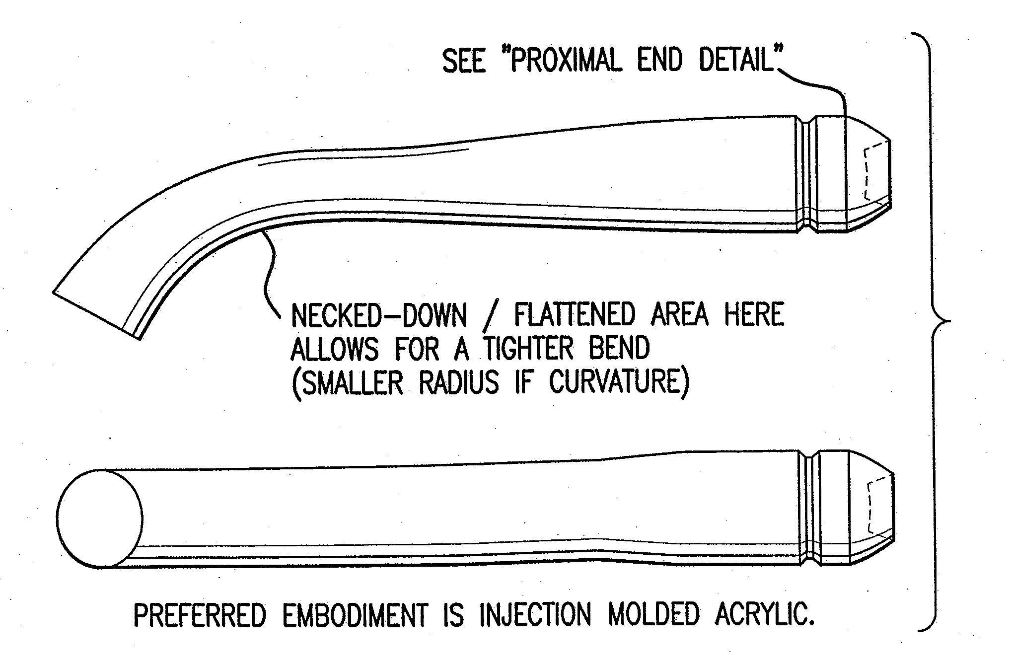
"The present invention provides a dental light guide that can be used for photo-initiation of light curing resins. The dental light guide has an entrance area, a lens, at least one reflector, a light pipe, and an exit area. The dental light guide can be made of acrylic, glass, or plastic and can have a multi-piece design. The dental light guide can be attached to an image conduit by a metal sleeve. The invention also provides an apparatus for providing light for photo-initiation of light curing resins, which includes a light source and a dental light guide. The dental light guide can be used for dental treatments such as dental restorations, dental implants, and dental veneers."

Problems solved by technology

Practical factors and physical limitations of both doctor and patient often dictate the design of the light guides and light-curing units used in modern dentistry.
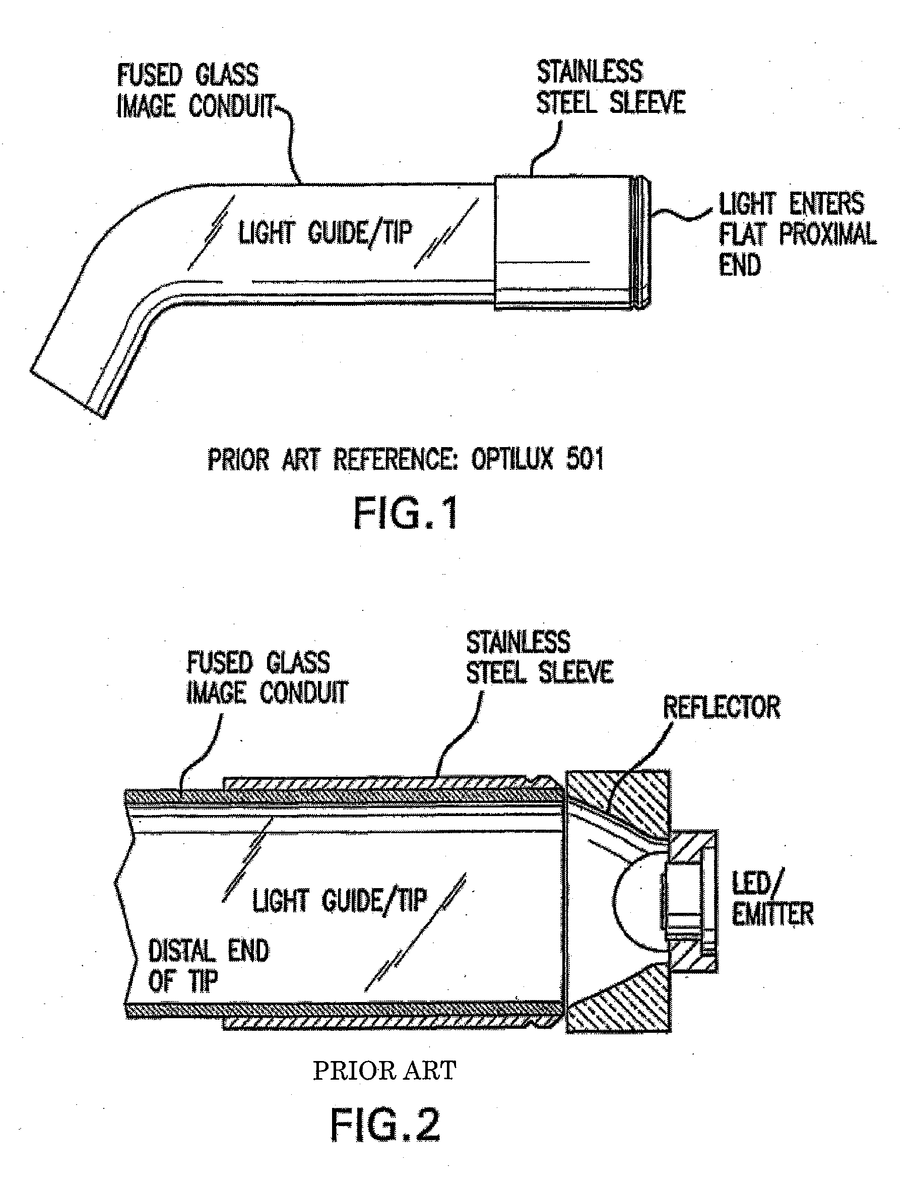
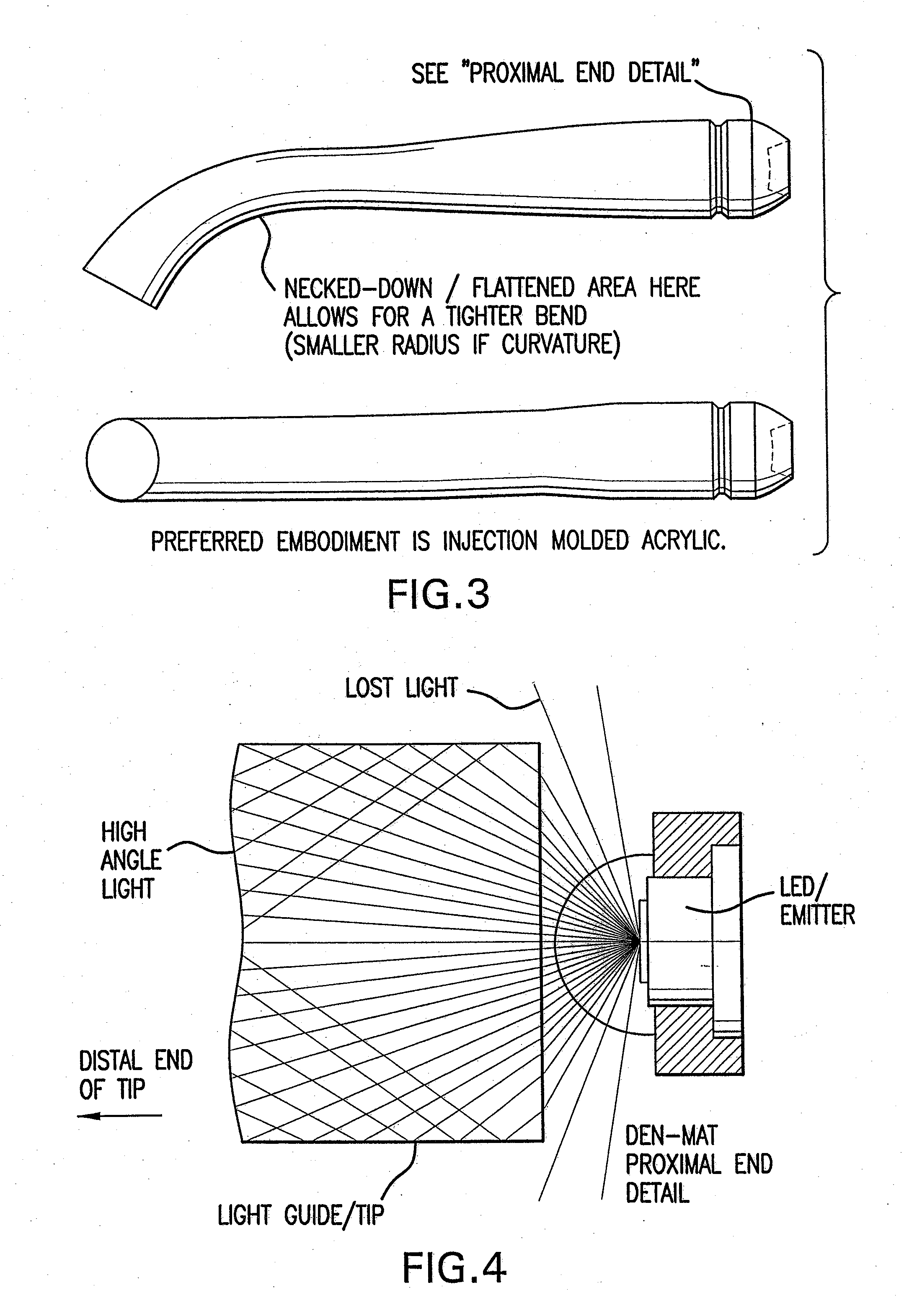
Conventional light guides are not as efficient as the instantly disclosed light guide as they typically produce high angle light that results in loss of light energy due to multiple reflections and the escape of light from the apparatus.
Light sources such as tungsten halogen, metal halide, and xenon are not very efficient at producing light energy within the spectral range useful for dental photo-polymerization and tooth whitening.
This is expensive and also increases the size of the device.

Method used


Image

  • Dental Light Guide
  • Dental Light Guide
  • Dental Light Guide

Examples


example 1

[0050]It has been demonstrated that light intensity (mW / cm2) disperses rapidly with distance from these light sources. The exit angle of the light as it leaves the light source contributes greatly to this. As the beam spread increases the light looses intensity rapidly. This is clinically significant to the practicing dentist and their patients. The bottom floor of a typical preparation may be a minimum of 2 mm deep or more. If the light intensity is too low at the bottom of the filling the composite material may not receive enough energy to adequately cure. Even if the composite is placed directly on the surface of the tooth the dentist holds the distal end of the light guide approximately 2 mm away to keep the composite from adhering to it. The clinical advantage of the present invention is that the light intensity mW / cm2) increases at 2 mm away from the surface and stays higher as distance increases. This facilitates complete curing of the composite. The results of this experimen...

example 2

[0051]The effect of light collimation with an embodiment of the instant invention (identified in FIG. 11 as “Allegro”) on a composite (Heliomolar) that is hard to cure is shown in the FIG. 11. FIG. 11 also compares the embodiment of the instant invention to the other 3 best LED-curing lights on the market. The instant invention is clearly superior. The composite was cured at a distance of 6 mm. See FIG. 12. The vertical axis shows the hardness value. Knoop Hardness (KHN) is considered, by academics, the most accurate test of composite hardness. Greater hardness means the composite has polymerized to a greater degree. This improves strength and wear and decreases the likelihood of sensitivity. The bottom of the sample is actually 8 mm away from the distal end of the tip.


PUM


Abstract

The present invention is a device that attaches to a light source to transmit and distribute light energy to the surface or internal chamber of a tooth for the purpose of photo-initiation of light curing resins and dental tooth whitening. More particularly, the invention may be used with a single or multiple Light Emitting Diode(s) to more efficiently collect and transmit the light energy emitted by the LED(s) resulting in increased total energy, uniform illumination, and collimation of the light energy delivered to the tooth.

Description

REFERENCE TO RELATED APPLICATION[0001]This application claims the benefit of U.S. Provisional Application No. 60 / 427,210, filed Nov. 19, 2002, which is hereby incorporated by reference.FIELD OF INVENTION[0002]This invention relates to light guides and light-curing apparatus for producing a beam of light for photo-initiating a light curing dental composition. In particular, the present invention is a device that attaches to a Light Emitting Diode (LED) light source to transmit and distribute light energy to the surface or internal chamber of a tooth for the purpose of photo-initiation of light curing resins and dental tooth whitening.BACKGROUND[0003]Dentistry relies on light curing resins as sealants, adhesives, and as filler material for filling dental cavities. Light curing material is cured by exposure to radiant energy in spectral range tailored to the composition of the material. A light-curing unit containing a reflector lamp is used to irradiate the light curing material by di...

Claims


Application Information

Patent Timeline
Patent Type & Authority Applications(United States)
IPC IPC(8): A61B1/06A61C13/15F21V8/00G02B6/42
CPCA61C19/004G02B6/4298G02B6/0006A61C19/066
Inventor WEST, JOHNGANAJA, SCOTT
Owner DEN MAT HLDG
Learn More