Reflector and apparatus including the reflector
a technology of reflector and reflector body, which is applied in the field of reflectors, can solve the problem of insufficient reflectance of the body,
- Summary
- Abstract
- Description
- Claims
- Application Information
AI Technical Summary
Benefits of technology
Problems solved by technology
Method used
Image
Examples
embodiment 1
[0105]FIG. 11 schematically illustrates the configuration of a heater 70 according to a first preferred embodiment of the present invention. The heater 70 includes a heating wire 71 and a reflective plate 72.
[0106]The heating wire 71 is a heat source. The reflective plate 72 is provided so as to reflect an infrared ray, radiated from the heating wire 71, outside of this heater 70, and may be made of steel, for example.
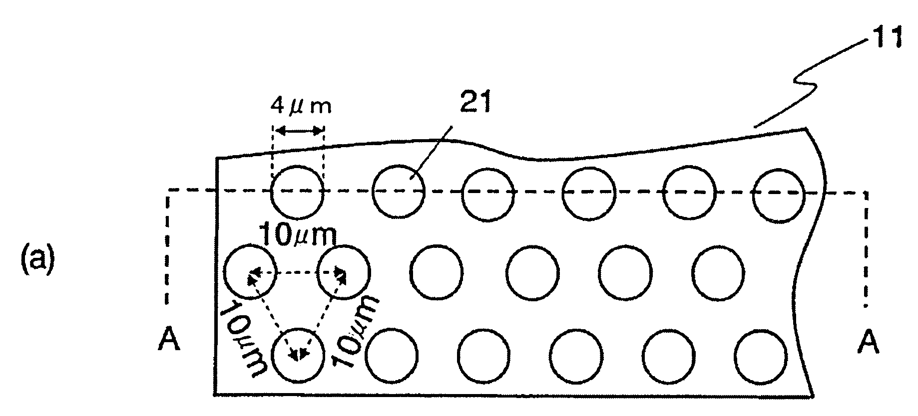
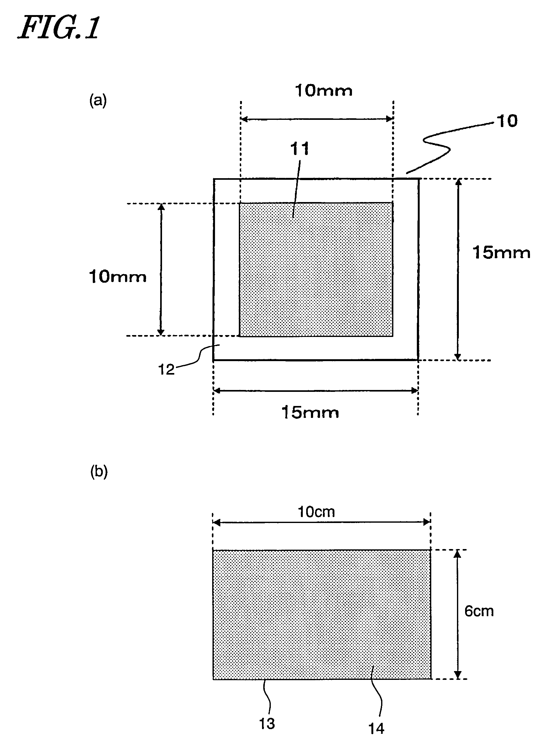
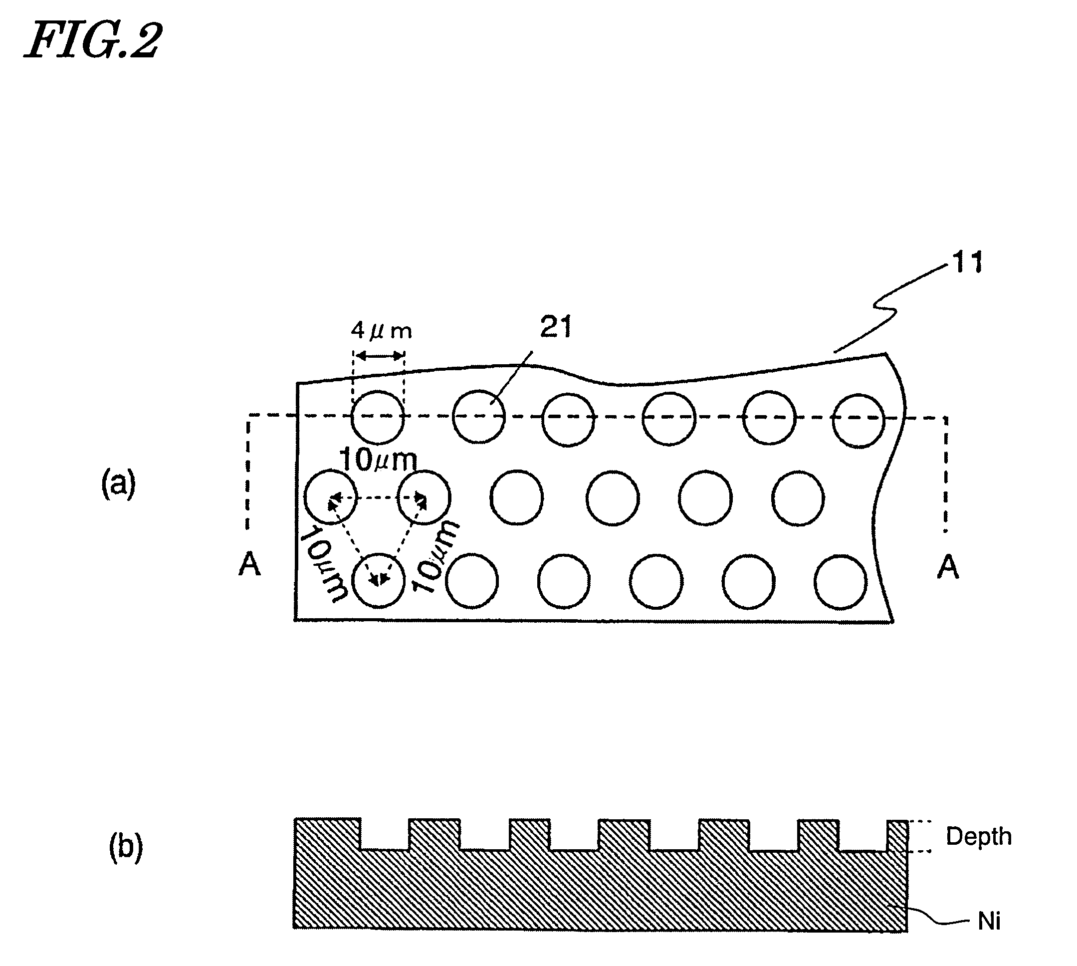
[0107]On the surface of the reflective plate 72, arranged are cavities 73, which include the cavities 21 of the cavity portion 11 shown in FIGS. l(a), 2(a) and 2(b).
[0108]The heater 70 is used mainly to warm a human being. That is why the cavities 73 preferably have a diameter of approximately 3 μm. This is because the human skin absorbs radiations with wavelengths of 6 μm or more by nature. The depth of the cavities 73 is determined by the aspect ratio that should be set for the cavities 73. As described above, the cavities 73 preferably have an aspect ratio of 0.17 t...
embodiment 2
[0111]FIG. 12 schematically illustrates the configuration of a reflective sheet 80 according to a second preferred embodiment of the present invention. This reflective sheet 80 has flexibility and is foldable. A roll of reflective sheet 80 that has been wound up is illustrated in FIG. 12 as an example.
[0112]The reflective sheet 80 is a stack of a reflective layer 82 and a resin layer 83. The reflective layer 82 defines the surface of the reflective sheet 80 and may be made of aluminum foil, for example. On the (reflective) surface of the reflective layer 82, arranged are a number of cavities 81, which have an aspect ratio of 0.7 or less. The lowest permissible aspect ratio is preferably 0.17. The foil may have any thickness as long as the thickness is greater than the skin depth of the foil material used and makes the sheet foldable in use. For example, the thickness is preferably in the range of 1 μm to 500 μm in practice.
[0113]The resin layer 83 is arranged behind the reflective l...
embodiment 3
[0121]Hereinafter, a preferred embodiment of a reflector to be exposed to more intense heat than the counterparts of the first and second preferred embodiments will be described.
[0122]In a conventional electric furnace, such as that disclosed in Japanese Patent Application Laid-Open Publication No. 8-14764, a metal such as gold is evaporated on the surface of a transparent glass enclosure that is arranged so as to surround a heat generator. And a layer of this evaporated metal reflects the thermal radiation of infrared rays back to the heat generator, thereby heating the object.
[0123]However, gold has a melting point of 1,064° C., and therefore, it is difficult to realize a furnace that can withstand the heat of more than 1,000° C. . Besides, since gold is an expensive material, the furnace product itself should be expensive. Meanwhile, another electric furnace, disclosed in the same document, surrounds a heat source with a metallic wall of aluminum, for example, thereby reflecting ...
PUM
 Abstract
Description
Claims
Application Information
 - R&D
- Intellectual Property
- Life Sciences
- Materials
- Tech Scout
- Unparalleled Data Quality
- Higher Quality Content
- 60% Fewer Hallucinations
Browse by: Latest US Patents, China's latest patents, Technical Efficacy Thesaurus, Application Domain, Technology Topic, Popular Technical Reports.
© 2025 PatSnap. All rights reserved.Legal|Privacy policy|Modern Slavery Act Transparency Statement|Sitemap|About US| Contact US: help@patsnap.com


