
Varible focus lens

a focus lens and variable technology, applied in the field of variable focus lenses, can solve the problems of large switching voltage needed to obtain a sufficient amount, and the effect of reducing the number of lenses, improving the reflectivity of the reflective lens, and different indices of refraction

Inactive Publication Date: 2009-02-19
KONINKLIJKE PHILIPS ELECTRONICS NV
View PDF5 Cites 2 Cited by
  • Summary
  • Abstract
  • Description
  • Claims
  • Application Information

AI Technical Summary

Benefits of technology

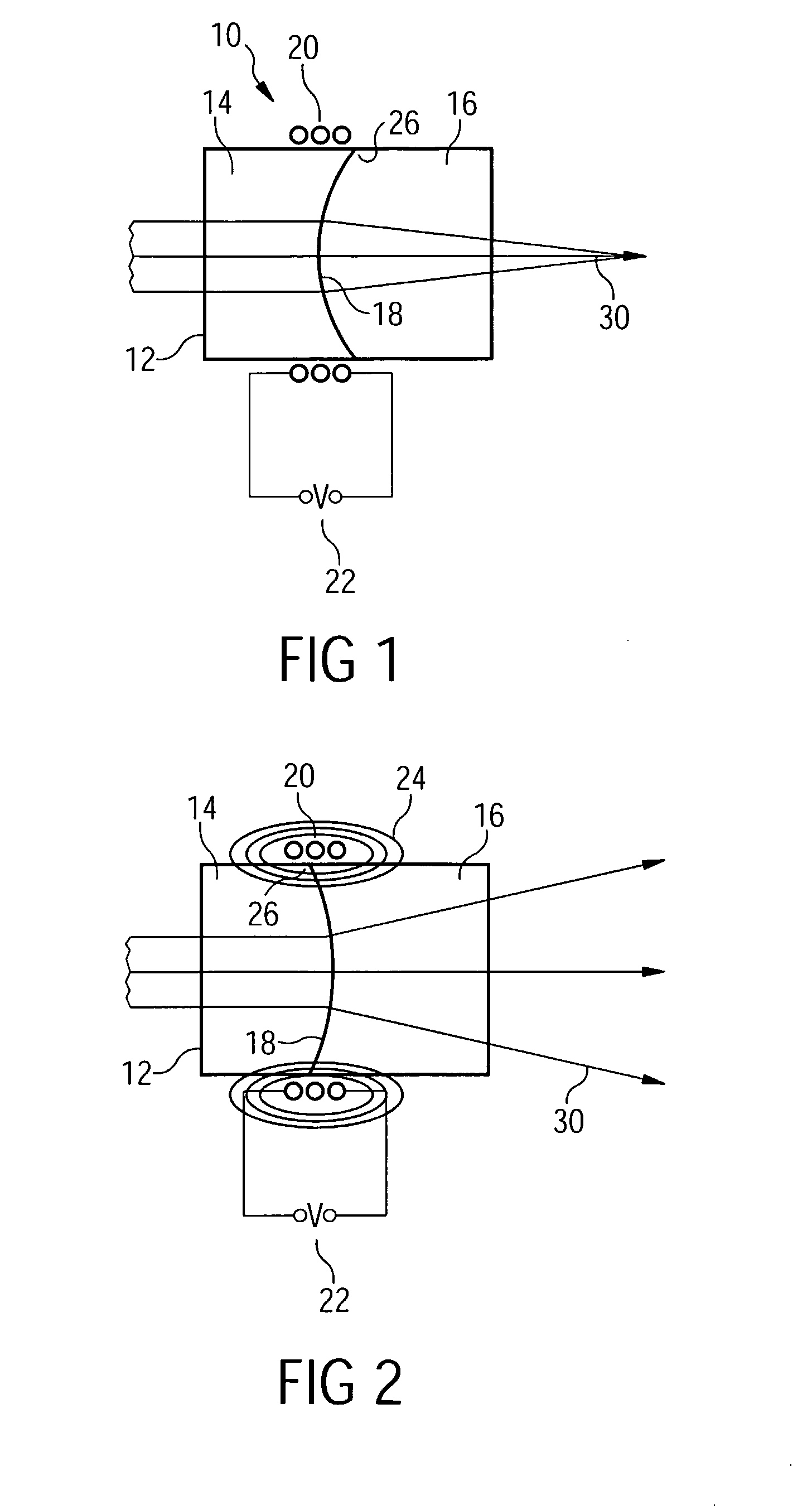
[0008]In accordance with the present invention, there is provided a variable focus lens comprising a fluid chamber containing a first fluid and a second fluid, the fluids being non-miscible and in contact over a meniscus and the second fluid being able to alter its shape on the influence of a magnetic field, and means for applying a gradient magnetic field over at least a part of the fluid chamber, thereby inducing a magnetic flux maximizing movement of the fluids, such that the shape of the meniscus varies in dependence on the magnetic field. Thus, by applying a magnetic field, the focus of the lens can be altered due to the induced meniscus change. In principle, all fluids having a sufficient magnetic moment can be employed with the present invention.
[0010]The present invention is particularly advantageous with relation to an embodiment, wherein the fluid chamber comprising a substantially cylindrical wall, and the means for applying a gradient magnetic field comprising at least one coil to which a voltage can be applied in order to generate the gradient magnetic field. Thus, the magnetic field can easily be generated and varied by a variable voltage.
[0011]According to a preferred embodiment of the present invention the gradient magnetic field is substantially localized to a vertex region of the meniscus. It is sufficient to produce a magnetic field gradient near the vertex in order to alter the whole shape of the meniscus. Therefore, it is useful to substantially localize the magnetic field to this region, thereby reducing the total magnetic field strength required.
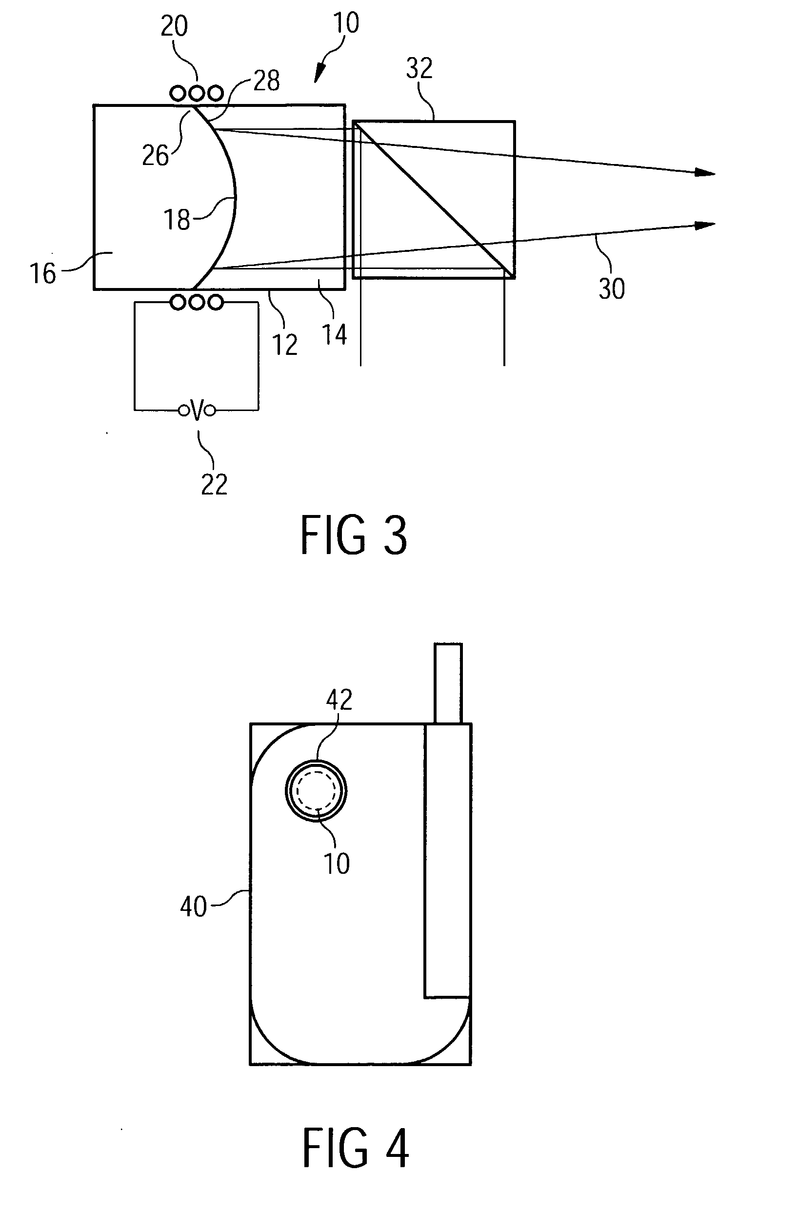
[0014]In this context it is particularly advantageous that a metal liquid like film is trapped at at least part of the interface between the two liquids in order to form a mirror surface. Such metal liquid like films (MELLF) consist of small particles that are trapped at the interface between the two liquids forming a mirror surface. Thereby the reflective properties of the reflective lens are improved.
[0015]According to a still further embodiment a magnetic field is applied in order to shift particles that are responsible for the non-transparency of the ferrofluid into the direction of the vertex region of the meniscus, thereby generating a transparent region in the second fluid, the first fluid and the transparent region of the second fluid having different indices of refraction. By this measure, even with a non-transparent ferrofluid the operation of the variable focus lens according to the invention as a refractive lens is possible.
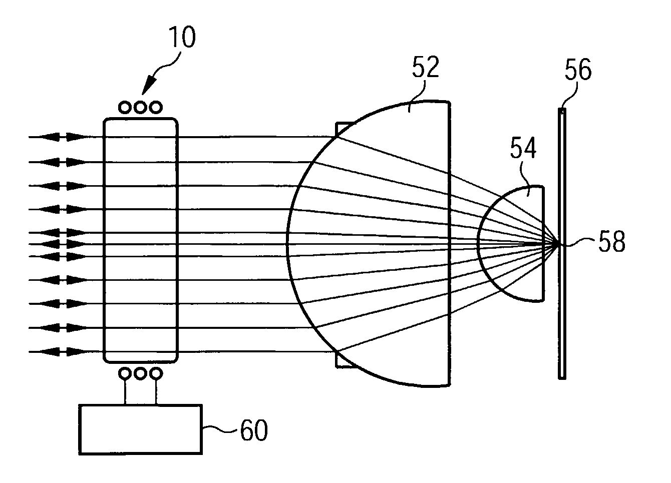
[0018]The variable focus lens can be advantageously implemented in an optical device and more particularly in an image capture device. For example, mobile telephones that are provided with an image capturing feature can be provided with a variable focus lens according to the present invention in order to maintain the small size of these devices. However, also different image capturing devices, such as normal cameras or video cameras can be provided with an optical device according to the present invention, since also in case of these devices it is desirable to avoid mechanical moving parts, to reduce the devices in size, to provide the possibility of a quick and considerable focus change, and to obtain this focus change on a low voltage level.

Problems solved by technology

However, a drawback of electrowetting lenses is the relative large switching voltage that is needed to obtain a sufficient variation in the shape of the meniscus.

Method used


Image

  • Varible focus lens
  • Varible focus lens
  • Varible focus lens

Examples


Embodiment Construction

[0026]FIG. 1 shows a variable focus lens in accordance with an embodiment of the present invention in schematic cross section in a first switching configuration. The cross section shows an axial cut through the lens 10. The lens 10 comprises a cylindrical fluid chamber 12. In the fluid chamber 12 a first fluid 14 and a second fluid 16 are provided, the second fluid being a ferrofluid. The fluids are non-miscible. Thus, at the interface between the fluids 14, 16, a meniscus 18 is formed. The inner wall of the fluid chamber 12 may be coated with a fluid contact layer (not shown), which reduces the hysteresis in the contact angle of the meniscus with the cylindrical wall of the fluid chamber 12. The fluid contact layer is preferably formed from an amorphous fluorocarbon such as Teflon™ AF1600 produced by Dupont™. The fluid contact layer has a preferred thickness of between 5 nm and 50 μm. The AF1600 coating may be produced by successive dip coating of the fluid chamber 12, which forms ...


PUM


Abstract

A variable focus (10) lens comprising a fluid chamber (12) containing a first fluid (14) and a second fluid (16) is disclosed. The fluids are non-miscible and in contact over a meniscus (18) and the second fluid is able to alter its shape on the influence of a magnetic field. The second fluid is preferably a ferrofluid. Means (20, 22) for applying a gradient magnetic field (24) over at least a part of the fluid chamber are provided that are capable of inducing a magnetic flux maximizing movement of the fluids, such that the shape of the meniscus varies in dependence on the magnetic field.

Description

FIELD OF THE INVENTION[0001]The present invention relates to a variable focus lens comprising a first fluid and a second fluid, the fluids being non-miscible and in contact over a meniscus. By changing the shape of the meniscus, the focus of the lens can be varied.BACKGROUND OF THE INVENTION[0002]Prior art variable focus lenses are known as electrowetting lenses. These electrowetting lenses comprise a fluid chamber containing two non-miscible fluids that form a meniscus at the interface between these fluids. Thus, provided that the fluids have different indices of refraction, the system can act as a refractive lens. Since one of the fluids is electrically conductive while the other fluid is not, by applying an electrical field to the lens, the shape of the meniscus and thereby the focus of the lens can be varied.[0003]Electrowetting lenses are for example described in WO 03 / 069380 A1.[0004]Due to the low power consumption and the quick response to a varying voltage, electrowetting l...

Claims


Application Information

Patent Timeline
Patent Type & Authority Applications(United States)
IPC IPC(8): H04N5/232G02B3/14G02B26/02
CPCG02B26/005G02B3/14
Inventor HENDRIKS, BERNARDUS HENDRIKUS WILHELMUSKUIPER, STEIN
Owner KONINKLIJKE PHILIPS ELECTRONICS NV
Learn More