Eureka AIR delivers breakthrough ideas for toughest innovation challenges, trusted by R&D personnel around the world.

Light emitting diode (LED) with longitudinal package structure

a technology of light emitting diodes and longitudinal packages, applied in semiconductor devices, lighting and heating apparatus, instruments, etc., to achieve the effect of enhancing illuminative efficiency

Inactive Publication Date: 2009-02-19
YEH HSIN HUI
View PDF4 Cites 18 Cited by
  • Summary
  • Abstract
  • Description
  • Claims
  • Application Information

AI Technical Summary

Benefits of technology

[0008]According to the problems described above, the main object of the present invention is to provide a light emitting diode (LED) with longitudinal package structure used to decrease the covered portion of the LED and enhance the illuminative efficiency.
[0009]Another object of the present invention is to produce the transparent carrier substrate and LED at the same time and reduce the package time of the LED.
[0010]Another object of the present invention is to saw the LED package structure by customers' request after the LED is electrically connected to the carrier substrate without increasing the package time.

Problems solved by technology

But how to enhance the extraction efficiency of the LED package structure to get higher overall efficiency in the quantum efficiency inside the semiconductor chip of the LED is the important issue in current technology.

Method used


Image

  • Light emitting diode (LED) with longitudinal package structure
  • Light emitting diode (LED) with longitudinal package structure
  • Light emitting diode (LED) with longitudinal package structure

Examples


Embodiment Construction

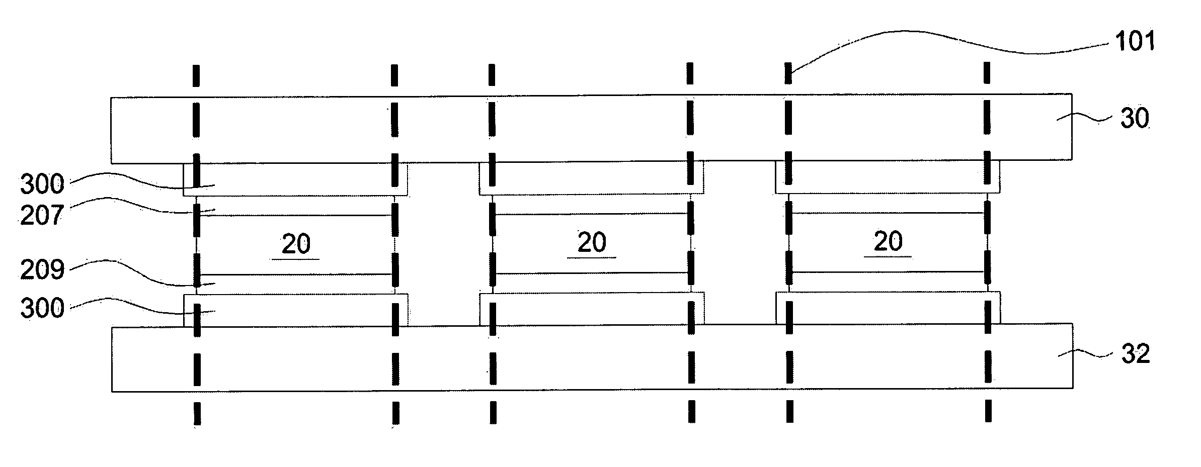
[0024]The following detailed description of the present invention describes a light emitting diode package structure necessary to provide an understanding of the present invention, but does not cover a complete structure composition and the operating theory. The portions relating to the conventional techniques are briefly described, and the parts of the drawings are not proportionally drafted. While embodiments are discussed, it is not intended to limit the scope of the present invention. Except expressly restricting the amount of the components, it is appreciated that the quantity of the disclosed components may be greater than that disclosed.

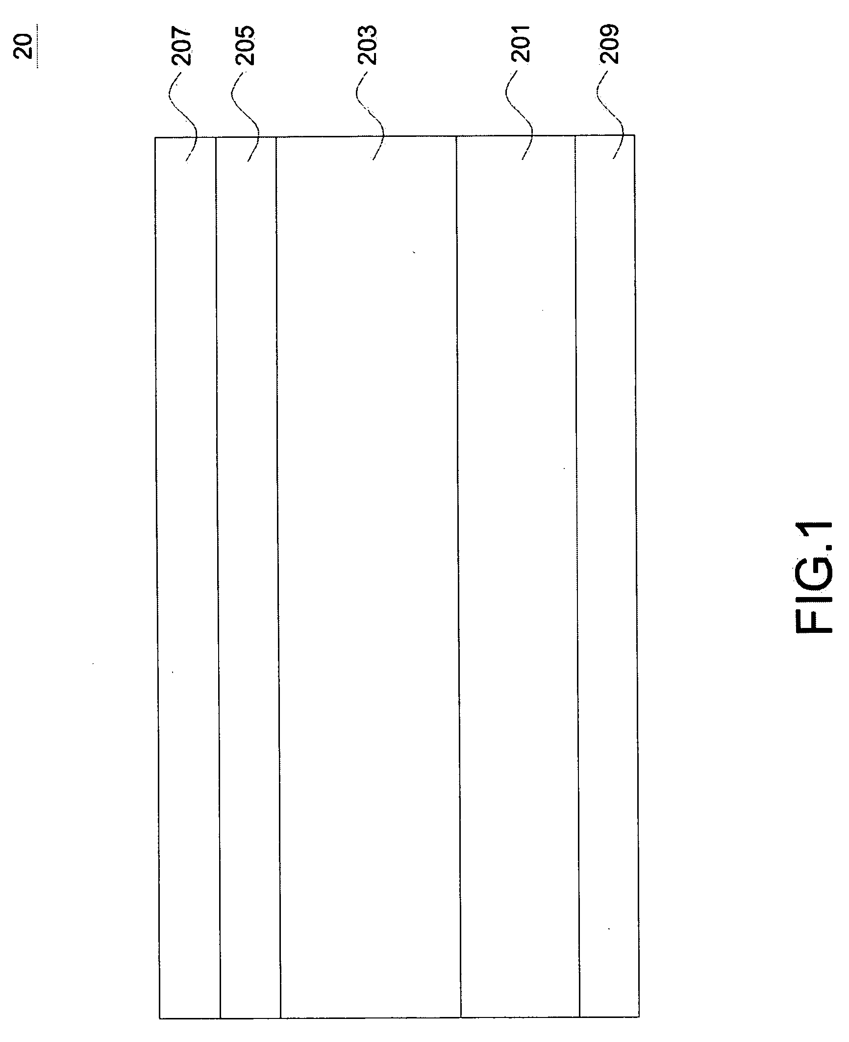
[0025]Please referring to FIG. 1, it is a sectional view showing a light emitting diode (LED) structure. The LED structure 20 includes a substrate 201, an epitaxy stacked layer 203, a transparent conductive layer 205, an electrode 207. The epitaxy stacked layer 203 is formed on the substrate 201. The transparent conductive layer 205 is formed ...


PUM


Abstract

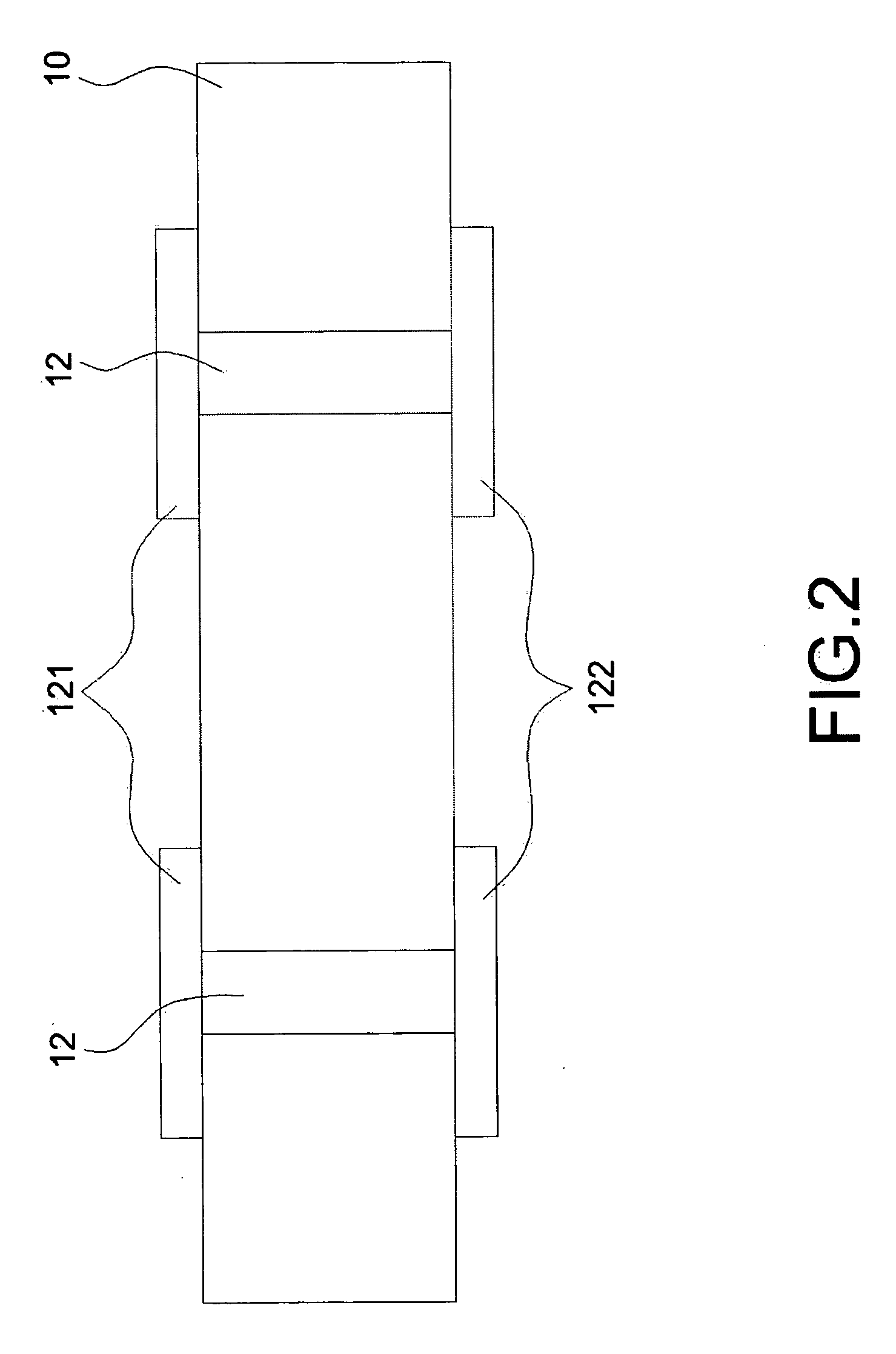
The present invention provides erected LED package structure, which includes: a carrier substrate having a first surface, a second surface and a plurality of through holes passed through the first surface and the second surface of the carrier substrate, and the conductive material filled with each of the through holes; a LED having a semiconductor layer capable of the light emitting and an N electrode and a P electrode formed on the two sides of the semiconductor layer thereon; a first transparent carrier substrate having a metal layer thereon, in which the metal layer electrically connected to the N electrode of the LED and to the conductive material which is formed on the first surface of the carrier substrate; a second transparent carrier substrate having another metal layer thereon, in which another metal layer electrically connected to the P electrode of the LED and to another conductive material which is formed on the first surface of the carrier substrate; and a plurality of connecting elements electrically connected to the plurality of conductive material which is formed on the second surface of the carrier substrate.

Description

BACKGROUND OF THE INVENTION[0001]1. Field of the Invention[0002]The present invention is a light emitting diode (LED) package structure and more particularly is a package structure that the LED is vertically disposed to form a LED with longitudinal package structure.[0003]2. Description of the Prior Art[0004]Light emitting diode (LED) is a light emitting element is an illuminate element used to directly transform the electrical power to light power without transforming the electrical power to heat power. Therefore, LED is also called the luminescence emitting element. LED not only includes high illuminant efficiency but also is a micro solid state illuminator made in a semiconductor chip form. The voltage is inputted in two sides of the p-n junction and the current is able to flow through to generate electrons and holes flowing toward the p-n junction, and the electrons and holes are connected with the p-n junction to release photons.[0005]Generally, the illumination of the LED in t...

Claims


Application Information

Patent Timeline
IPC IPC(8): H01L33/00H01L33/46H01L33/56H01L33/62
CPCF21K9/00G09G3/14G09G3/32G09G2300/0452H01L33/46H01L2924/0002H01L33/56H01L33/62H01L2924/00
Inventor YEH, HSIN HUI
Owner YEH HSIN HUI
Why Eureka
Eureka Blog
Learn More