
Light fixture and lens assembly for same

a technology of light fixture and lens assembly, which is applied in the direction of lighting and heating apparatus, lighting support devices, light source combinations, etc., can solve the problems of large brightness of the surface of the lamp, the difficulty of adjusting the light intensity of the lamp, and the discomfort of employing such lamps, so as to increase the light efficiency of the light fixture, diffuse the light relatively uniformly, and efficiently distribute the effect of ligh

Active Publication Date: 2007-06-12
ABL IP HLDG
View PDF64 Cites 76 Cited by
  • Summary
  • Abstract
  • Description
  • Claims
  • Application Information

AI Technical Summary

Benefits of technology

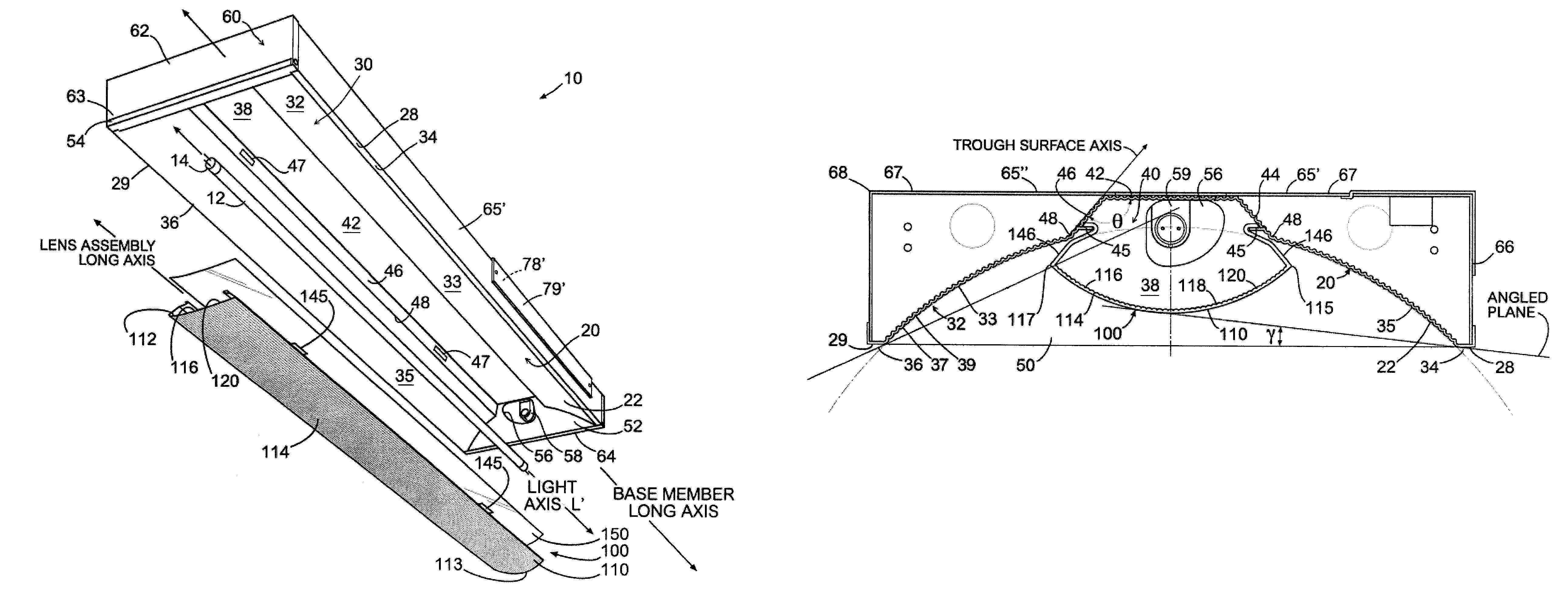
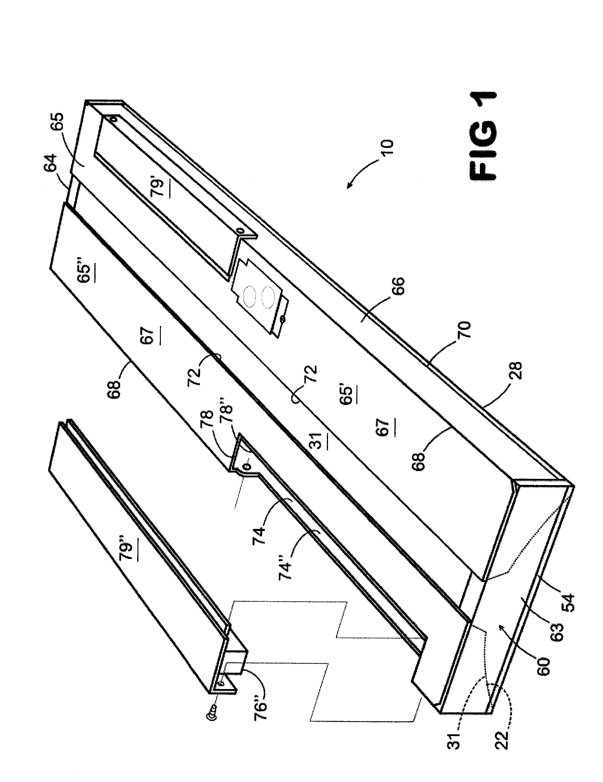
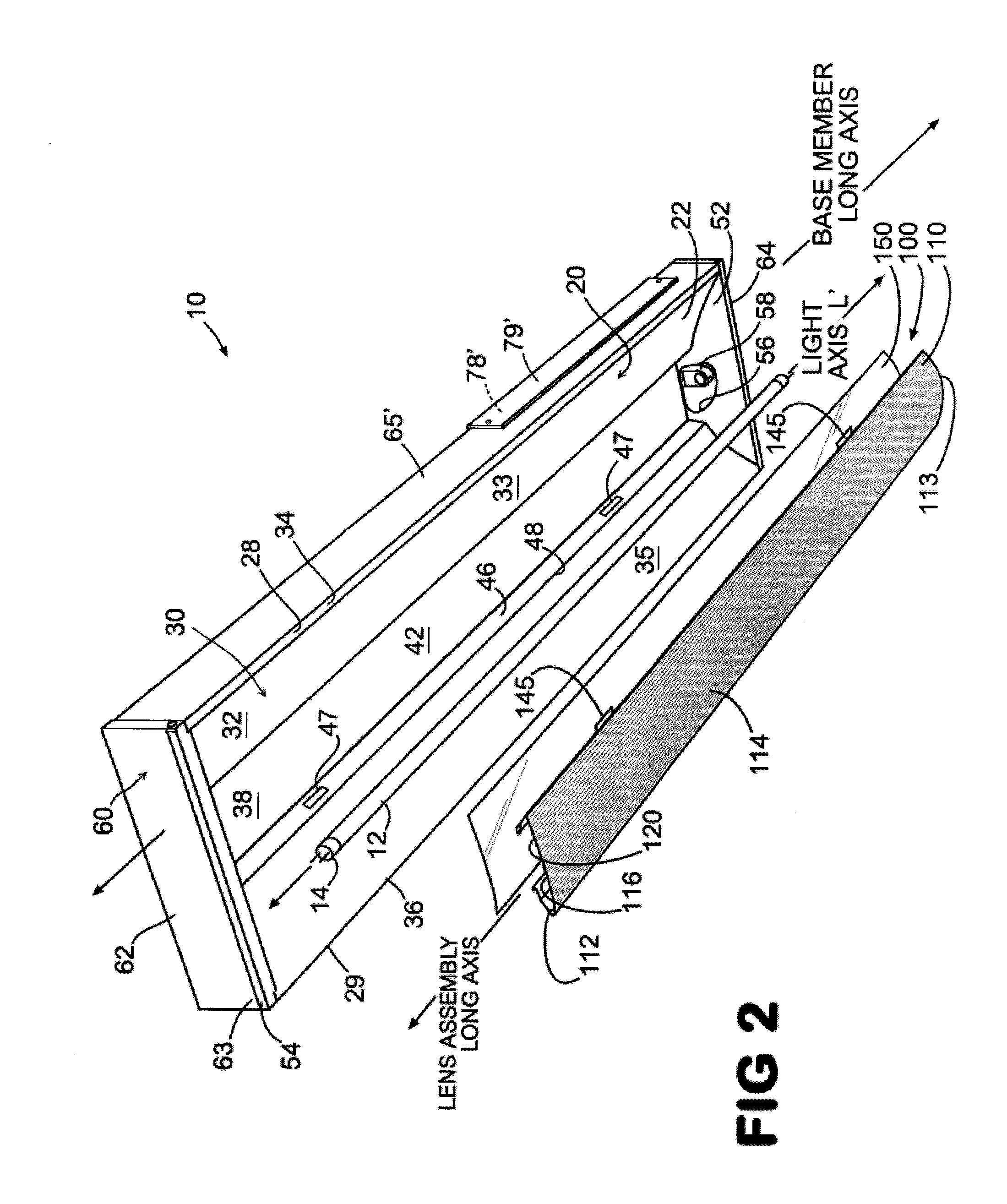
[0012]The present invention relates to a light fixture, or troffer, for efficiently distributing light emitted by a light source into an area to be illuminated. In one general aspect of the invention, the light fixture includes a reflector assembly that supports the light source. The light fixture may also include a lens assembly positioned with respect to a portion of the reflector assembly to receive light emitted by the light source and distribute it such that glare is further reduced. In a preferred embodiment, the lens assembly receives and distributes substantially all of the light emitted by the light source.
[0016]The lens is preferably detachably secured to a portion of the reflector assembly in overlying registration with the light source. In one aspect, a portion of the reflector assembly and a portion of the lens substantially enclose the light source so that, to an external viewer, the light source is substantially hidden from view. In one example, the array of linear extending prismatic elements presents to the external viewer an array of spaced, longitudinally extending shadows, or dark stripes, on the lens. Thus, the lens assembly of the present invention provides an aesthetically more pleasing appearance as well as efficiently distributing the light generated by the light source onto portions of the reflective surfaces of the reflector assembly and onto the desired area to be illuminated.
[0017]The lens assembly and reflector assembly of the present invention increase the light efficiency of the light fixture and diffuse the light relatively uniformly, which minimizes the “cave effect” commonly noted in areas using conventional parabolic light fixtures in the ceiling. In one embodiment, the light fixture or troffer of the present invention results in a luminare efficiency that is greater than 80%, preferably.

Problems solved by technology

Some conventional fluorescent lamps, however, have the significant drawback in that the lamp surface is bright when compared to a lamp of larger diameter.
The consequence of such bright surfaces is quite severe in applications where the lamps may be viewed directly.
Without adequate shielding, fixtures employing such lamps are very uncomfortable and produce direct and reflected glare that impairs the comfort of the lighting environment.
Heretofore, opaque shielding has been devised to cover or substantially surround a fluorescent lamp to mitigate problems associated with light sources of high surface brightness; however, such shielding defeats the advantages of a fluorescent lamp in regions of distribution where the lamp's surfaces are not directly viewed or do not set up reflected glare patterns.
Thus, with conventional shielding designs, the distribution efficiencies and high lumen output advantages of the fluorescent lamp can be substantially lost.
A further disadvantage to traditional parabolic and prismatic troffers is the presence of distracting dynamic changes in brightness level and pattern as seen by a moving observer in the architectural space.
This unaesthetic condition is remedied by indirect and direct-indirect fixture designs, but typically with a significant loss of efficiency.
However, such design approaches have the drawback that the extra lamps impair the designer's ability to achieve a desired light distribution from a given physical envelope and impose added burdens on lamp maintenance providers who must stock and handle two different types of lamps.
One of these is reduced lighting efficiency.
Further, when viewed directly at high viewing angles, a conventional parabolic fixture can appear very dim or, even, off.

Method used


Image

  • Light fixture and lens assembly for same
  • Light fixture and lens assembly for same
  • Light fixture and lens assembly for same

Examples


Embodiment Construction

[0041]The present invention is more particularly described in the following exemplary embodiments that are intended as illustrative only since numerous modifications and variations therein will be apparent to those skilled in the art. As used herein, “a,”“an,” or “the” can mean one or more, depending upon the context in which it is used. The preferred embodiments are now described with reference to the figures, in which like reference characters indicate like parts throughout the several views.

[0042]Ranges may be expressed herein as from “about” one particular value, and / or to “about” another particular value. When such a range is expressed, another embodiment includes from the one particular value and / or to the other particular value. Similarly, when values are expressed as approximations, by use of the antecedent “about,” it will be understood that the particular value forms another embodiment.

[0043]Referring to FIGS. 1-6, a light fixture 10 or troffer of the present invention for...


PUM


Abstract

A light fixture or troffer for directing light emitted from a light source toward an area to be illuminated, including a reflector assembly within which the light source is positioned and a lens assembly detachably secured to a portion of the reflector assembly such that a lens of the lens assembly overlies the light source and such that substantially all of the light emitted from the light source passes through the lens assembly. In one example, the lens includes a curved prismatic surface that can be oriented toward or away from the underlying light source.

Description

[0001]This application claims priority to and the benefit of U.S. Provisional Application No. 60 / 580,996, entitled “Light Fixture and Lens Assembly for Same,” filed on Jun. 18, 2004, which is incorporated in its entirety in this document by reference.BACKGROUND OF THE INVENTION[0002]1. Field of the Invention[0003]The present invention generally relates to light fixtures for illuminating architectural spaces. The invention has particular application in light fixtures using fluorescent lamps, such as the T5 linear fluorescent lamp, as the light source.[0004]2. Background Art[0005]Numerous light fixtures for architectural lighting applications are known. In the case of fixtures that provide direct lighting, the source of illumination may be visible in its entirety through an output aperture of the light fixture or shielded by elements such as parabolic baffles or lenses. A light fixture presently used in a typical office environment comprises a troffer with at least one fluorescent lam...

Claims


Application Information

Patent Timeline
Patent Type & Authority Patents(United States)
IPC IPC(8): F21S4/00F21S8/04F21V5/02F21V7/00F21V13/04F21V17/16F21V23/02
CPCF21S8/04F21V5/02F21V13/04F21Y2113/00F21V23/026F21Y2103/00F21V17/164
Inventor MAYFIELD, III, JOHN T.LYDECKER, STEPHEN H.TROTT, GARY D.GOULD, CARL T.LEADFORD, KEVINSHARP, CHRISTOPHER L.
Owner ABL IP HLDG
Learn More