
Plasma etching method and apparatus therefor

a technology of etching method and plasma, which is applied in the direction of fluid pressure measurement, instruments, vacuum gauges, etc., can solve the problem of not disclosing an etching method for etching silicon portions, and achieve the effect of increasing the etching rate of silicon portions

Inactive Publication Date: 2009-02-19
TOKYO ELECTRON LTD
View PDF13 Cites 226 Cited by
  • Summary
  • Abstract
  • Description
  • Claims
  • Application Information

AI Technical Summary

Benefits of technology

This approach allows for increased etching rates of silicon substrates, particularly in high-aspect-ratio holes, achieving rates exceeding 30 μm / min by reducing the partial pressure of SiF4 and increasing the availability of fluorine radicals, thus overcoming the limitations of previous methods.

Problems solved by technology

S61-032429 (page 2) discloses an etching method in which the silicon portion is etched by using SF6 gas as a process gas, wherein a partial pressure of the gas is set to 50 Pa and SF6 molecules are vibrated and excited with CO2 laser of 10 kw, but it is deficient in that it does not disclose an etching method for etching the silicon portion at high etching rate of more than 20 μm / min.

Method used


Image

  • Plasma etching method and apparatus therefor
  • Plasma etching method and apparatus therefor
  • Plasma etching method and apparatus therefor

Examples


Embodiment Construction

[0027]A plasma etching apparatus for explaining a plasma etching method will first be described in detail with reference to FIGS. 1 to 4. In this example, a magnetron RIE (Reactive Ion Etching) apparatus is used as a plasma etching apparatus. This etching apparatus has a stepped cylindrical process chamber (vacuum chamber) 1 made of, e.g., aluminum. The process chamber 1 is formed of two cylinders with different diameters that are connected to each other. The process chamber 1 has small-diameter upper chamber 1a and lower chamber 1b with a diameter larger than that of the upper chamber 1a. The process chamber 1 can be held in a vacuum state.

[0028]A support table 2 as a susceptor for horizontally holding a substrate to be processed W as an object to be processed is formed in the process chamber 1. The support table 2 is made of, e.g., aluminum and is supported by a support base 4 made of a conductor through an insulating plate 3. In addition, a focus ring 5 made of a material other t...


PUM


Abstract

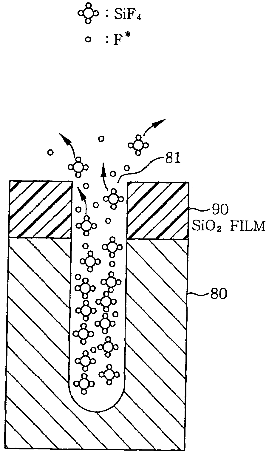
A fluorine-containing compound gas, e.g., SF6 gas, is converted into a plasma and a silicon portion of an object to be processed is etched by the plasma. At the same time, using a light source having a peak intensity of light in a wavelength range of light absorption of a reaction product, e.g., SiF4, for which, to be more precise, ranges from 9 μm to 10 μm, the light is irradiated onto a surface of an object to be processed from the light source. The SiF4 molecules absorb the light, become activated and gain kinetic energy to be used in gaining an easy escape from a hole. As a consequence, an amount (a partial pressure) of fluorine radicals (F*) used as an etchant is increased and an etching rate of a silicon is increased.

Description

FIELD OF THE INVENTION[0001]The present invention relates to a plasma etching method and an apparatus for converting a process gas including a fluorine-containing compound gas into a plasma and etching a silicon portion of an object to be processed with the plasma.BACKGROUND OF THE INVENTION[0002]Recently, a three-dimensional package device having a three-dimensional device structure has been developed. This three-dimensional package device is highly efficient in terms of space usage and is obtained by stacking single-crystal silicon (Si) substrates or the like having, e.g., logic or memory functions, to form a multi layered structure, and connecting the layers with interconnections.[0003]To realize three-dimensional package device, the interconnection through holes, diameters thereof ranging between 10 μm and 70 μm, must be formed in the silicon substrates, thickness thereof ranging between 100 μm and 200 μm, and this requires very high-rate etching.[0004]There is disclosed in Japa...

Claims


Application Information

Patent Timeline
Patent Type & Authority Applications(United States)
IPC IPC(8): B44C1/22
CPCH01J37/32082H01L21/3065H01J37/32678H01J37/32339
Inventor MARUYAMA, KOJI
Owner TOKYO ELECTRON LTD
Learn More