
Silicon casting apparatus

Inactive Publication Date: 2009-02-19
SUMCO SOLAR CORP
View PDF2 Cites 19 Cited by
  • Summary
  • Abstract
  • Description
  • Claims
  • Application Information

AI Technical Summary

Benefits of technology

[0014]An object of the present invention is to provide a silicon casting apparatus having a cold crucible which can extend the crucible life while heat quantity for melting the raw material is ensured by preventing the generation of the electric-discharge flaw in the surface of each strip-like element constituting the cold crucible, when the polycrystalline silicon is continuously cast by solidifying silicon as raw material after the silicon as raw material is melted by electromagnetic induction heating using the electrically-conductive bottomless cold crucible which is divided into a plurality of elements in a circumferential direction.
[0015]The inventors studied adoption of a crucible made of material having an excellent resistance to electrically discharging generated by the contact of the molten silicon with the crucible surface (surface of the each strip-like element), in other words, material in which the warping or damaging is hardly generated in the slits, as one of the means for solving the problems. The reason why they studied adoption of the crucible is that even if the electric discharging is generated, when the electric-discharge flaw is hardly generated due to the great resistance to the electric discharging, the slit warping or damaging is reduced to extend the cold crucible life, and the increase in facility costs can be suppressed.
[0016]In addition to the excellent electric conductivity and thermal conductivity, the conditions which should be possessed by the cold crucible include excellent hardness, strength, and wear-resistant property at high temperatures in order to prevent or suppress the generation of the electric-discharge flaw.
[0021]Accordingly, the material of the cold crucible is changed from pure copper to beryllium copper, the cold crucible is prepared, and the electromagnetic casting is actually performed. As a result, it is confirmed that the generation of the electric-discharge flaw is prevented to thereby substantially extend the cold crucible life.
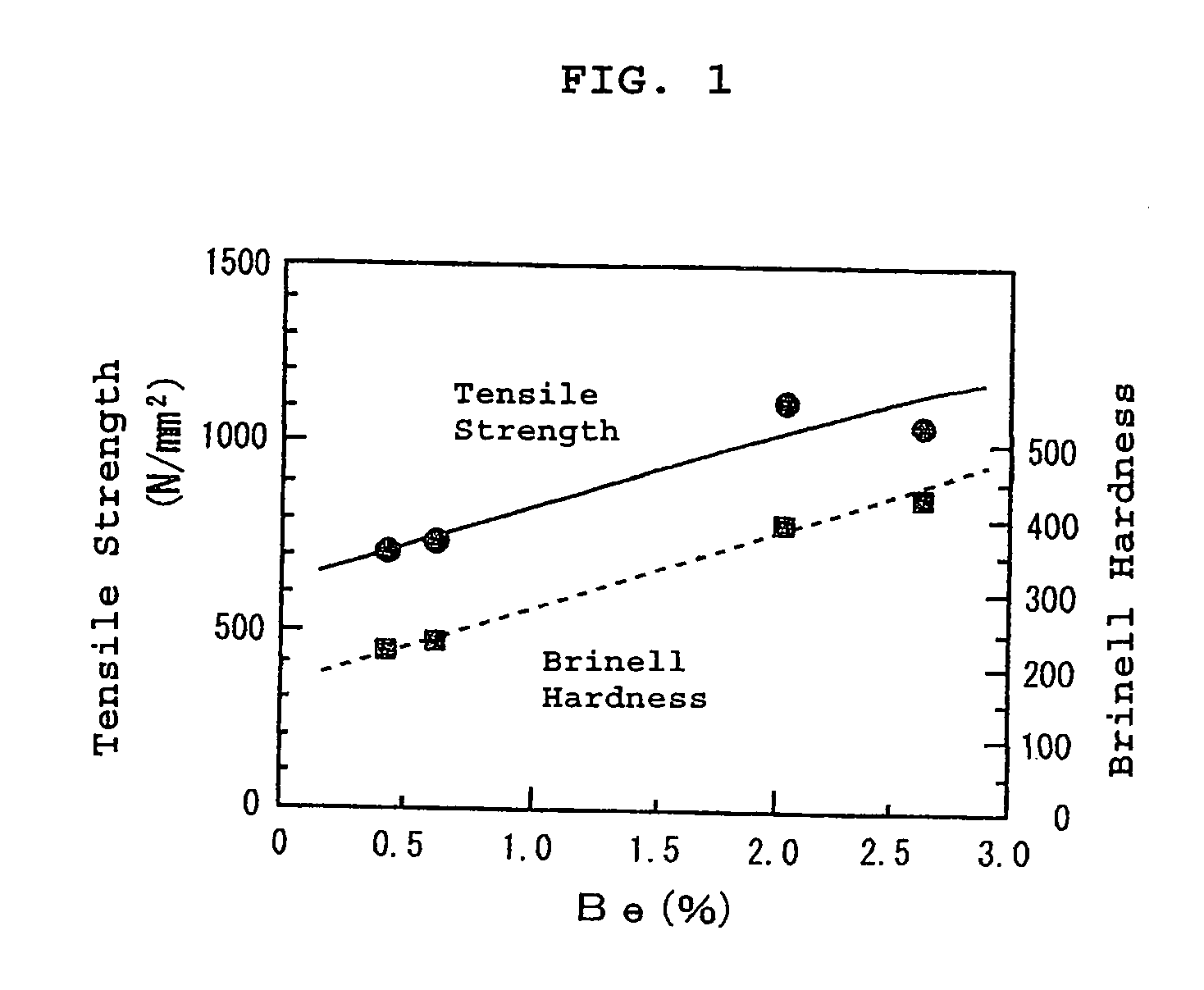
[0025]The silicon casting apparatus according to the present invention, as a vessel for melting the raw material, includes a bottomless cold crucible made of copper alloy containing beryllium, in which the crucible is divided into a plurality of elements in a circumferential direction. In performing the electromagnetic casting, the silicon casting apparatus can prevent effectively the generation of the electric-discharge flaw in comparison with the use of the conventional copper bottomless cold crucible.
[0026]Therefore, the crucible life can be remarkably extended to contribute to the facility cost reduction, and the heat quantity for melting the raw material can be ensured to stably perform the casting. Additionally, the impurity contamination can be prevented since the molten silicon scarcely contacts the crucible wall. Therefore, the silicon casting apparatus according to the present invention is suitable for the production of the solar-cell silicon ingot requiring high quality.

Problems solved by technology

However, when compared with the polycrystalline silicon, solar-cell production costs are increased since the silicon production costs are increased.
However, since the cast method is an ingot making method of solidifying the molten silicon with a quartz crucible or a graphite mold, impurity contamination is generated due to contact of the molten silicon with the wall of a container such as the crucible.
There is also a problem that a mold lubricant used to prevent fusion between the ingot and the mold is mixed into the molten silicon.
Additionally, since continuous casting can be hardly performed by the cast method, production efficiency is inevitably lowered.
However, in the actual operation, warping or damaging takes place in slits between the strip-like elements constituting the cold crucible.
Therefore, a frequent repair is required, and a crucible life is short, which increases facility costs.
The slit warping or damaging is caused by electric discharging which is generated by the contact of the molten silicon with the electrically-charged crucible surface (that is, surface of the each strip-like element).
When the slit is degraded due to the increase in electric-discharge flaw thus rendering the slit warping or damaging sorely, an eddy current generated in the molten silicon is weakened to decrease heat quantity for melting the raw material.
The casting becomes unstable to thereby lower the obtained ingot quality.

Method used


Image

  • Silicon casting apparatus
  • Silicon casting apparatus
  • Silicon casting apparatus

Examples


examples

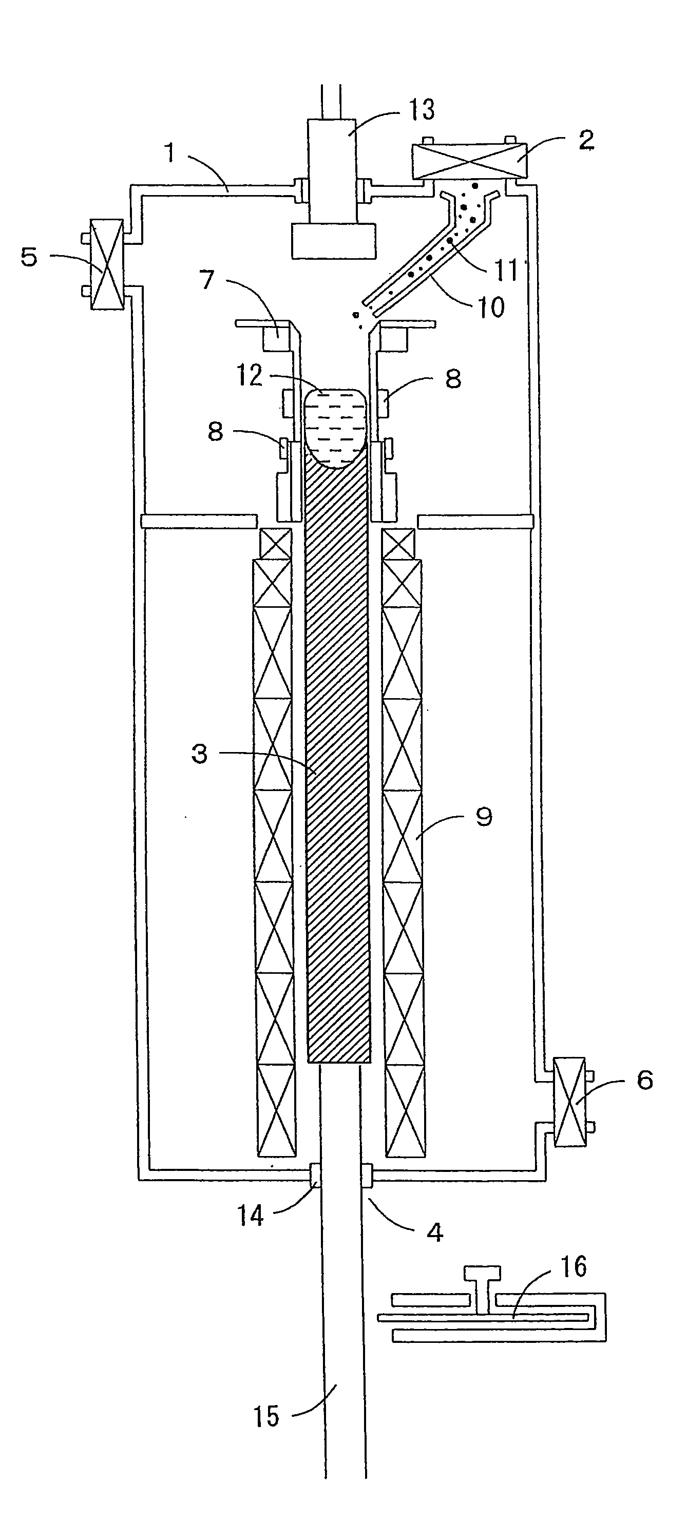
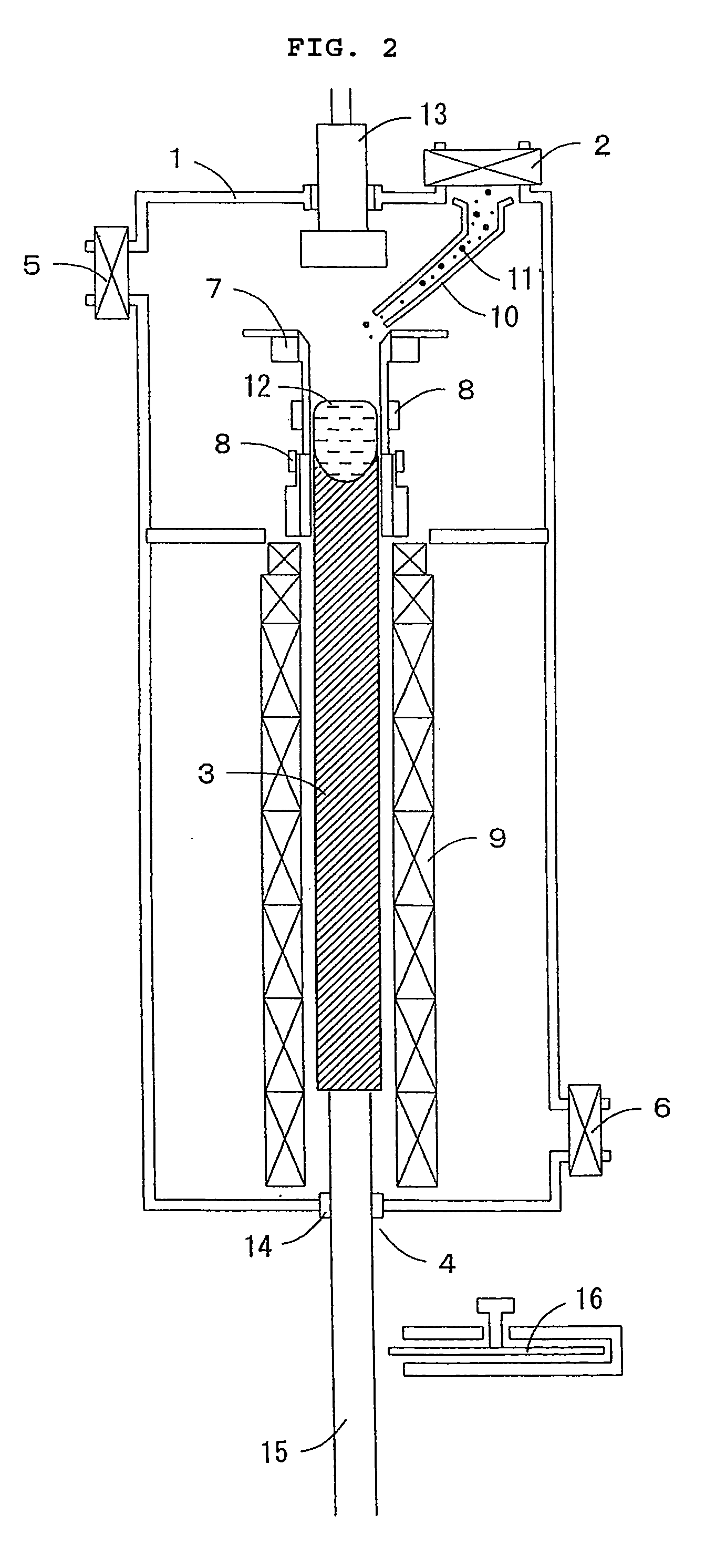
[0050]The electromagnetic casting was performed using the silicon casting apparatus of the present invention having the schematic configuration of FIG. 2, and the state of the slit deterioration associated with the repetitive use of the cooled mold and the mold life were investigated. Given that the use of the mold from the start to the end in the continuous casting is deemed to be one (1) time in the frequency of use, the mold life was evaluated in terms of the frequency of use in the casting.

[0051]The crucible made of beryllium copper equivalent defined in JIS H 3270 was used as the cold crucible made of copper alloy containing beryllium.

[0052]FIGS. 3A to 3C illustrate the progression of the deterioration of the slit portion in the copper cold crucible which is used for the purpose of comparison. FIG. 3A shows the normal slit portion before casting is performed, and FIGS. 3B and 3C show the slit portions after being used 6 and 8 times in the casting. The deterioration aggravates c...


PUM

PropertyMeasurementUnit
Percent by massaaaaaaaaaa
Electrical conductoraaaaaaaaaa

Abstract

In a silicon casting apparatus according to the present invention, silicon melted by electromagnetic induction heating is continuously solidified using an electrically-conductive bottomless cold crucible and an induction coil surrounding the cold crucible. The cold crucible is made of copper alloy containing beryllium (desirably containing beryllium of 0.1 to 5 mass %), whereby the generation of electric-discharge flaw can be effectively prevented in performing electromagnetic casting. The use of the silicon casting apparatus according to the present invention can greatly extend a crucible life to reduce facility costs. Additionally, a solar-cell silicon ingot can be produced with high quality.

Description

BACKGROUND OF THE INVENTION[0001]1. Field of the Invention[0002]The present invention relates to a silicon casting apparatus suitable for production of a solar-cell silicon ingot and the like. The silicon casting apparatus includes an electrically-conductive copper-alloy cold crucible divided into a plurality of elements in a circumferential direction, and is used when silicon as raw material is melted by electromagnetic induction heating and solidified to perform continuous casting of a polycrystalline silicon.[0003]2. Description of the Related Art[0004]A silicon crystal is used as a substrate material in almost all currently-produced solar cells. The silicon crystal is classified into a single crystal and a polycrystal. Usually, solar cells having higher efficiency in converting incident light energy into electric energy can be obtained when the single crystal is used as the substrate.[0005]The single-crystal silicon is produced by the Czochralski method, and a high-quality dislo...

Claims


Application Information

Patent Timeline
IPC IPC(8): B22D11/041
CPCC30B11/001C30B29/06C30B11/003C30B11/002
Inventor KIDA, MICHIOSASATANI, KENICHIYOSHIHARA, MITSUOONIZUKA, TOMOHIRO
Owner SUMCO SOLAR CORP
Learn More