Apparatus and method for plasma doping
a plasma doping apparatus and plasma technology, applied in the field of plasma doping apparatus, can solve the problems of difficult to make the dose amount of plasma doping impurities the dose amount of plasma doping impurities is hardly uniform over the substrate main surface, so as to achieve high precision the effect of sheet resistance distribution
- Summary
- Abstract
- Description
- Claims
- Application Information
AI Technical Summary
Benefits of technology
Problems solved by technology
Method used
Image
Examples
first embodiment
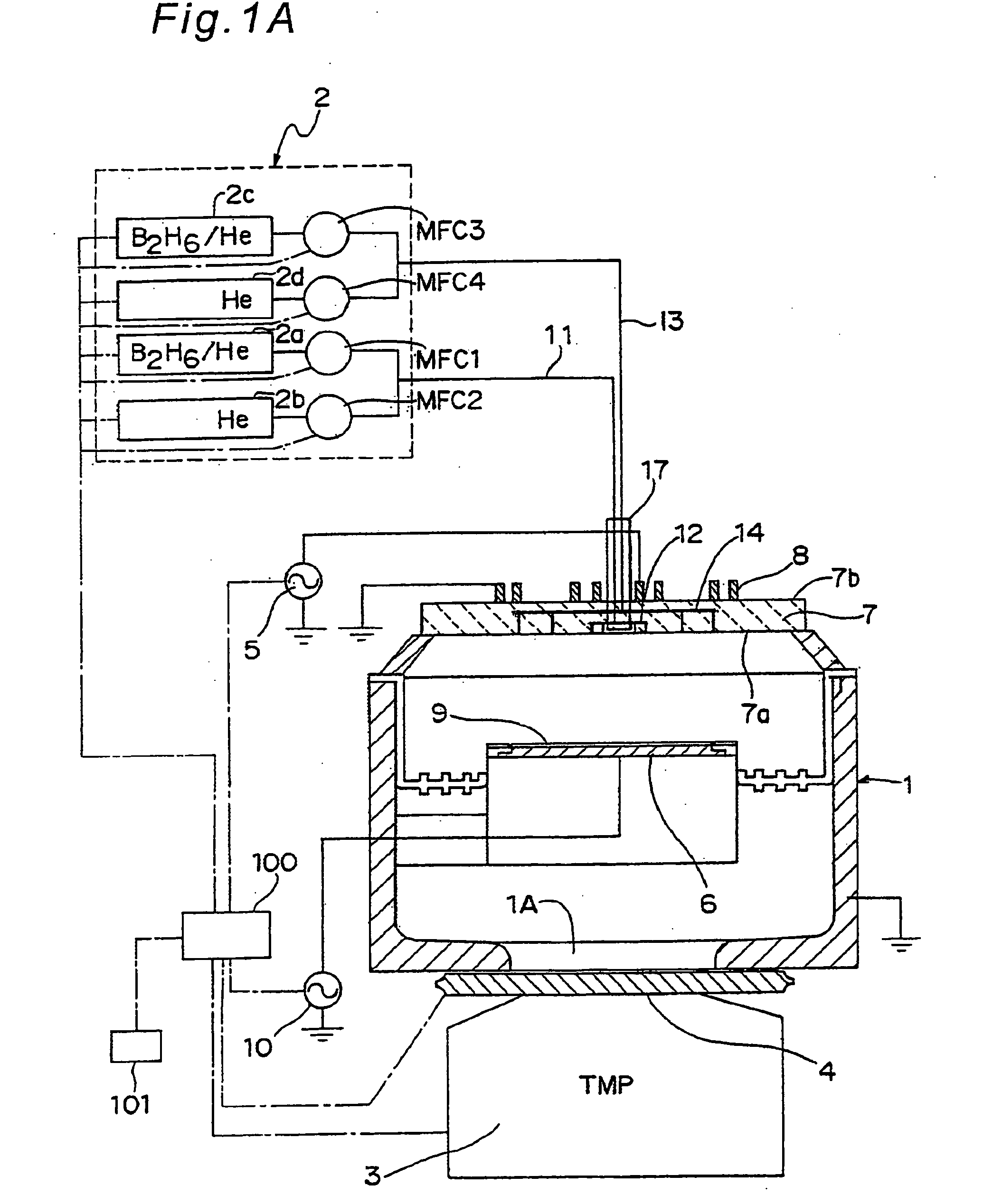
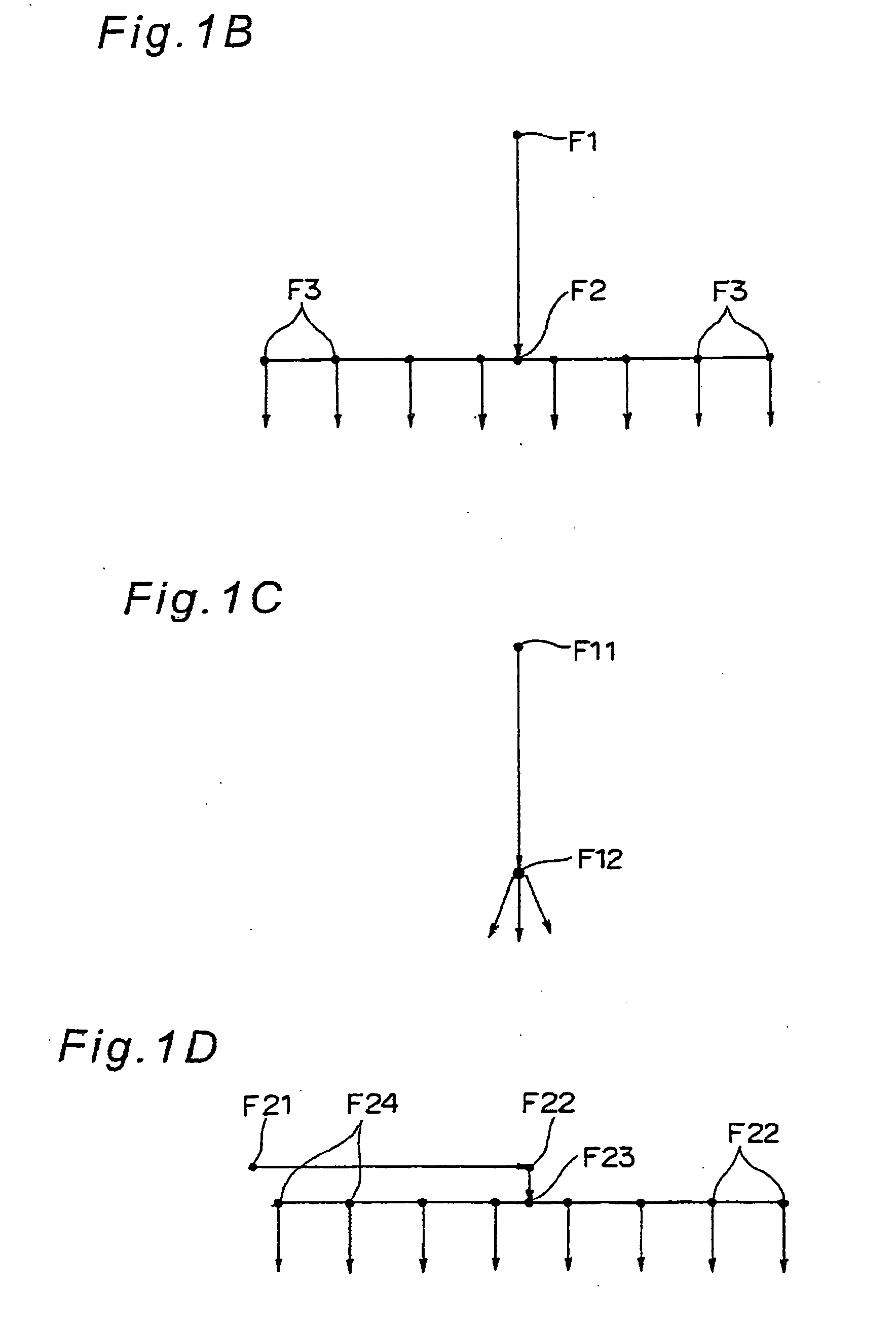
[0221]The apparatus and the method for plasma doping according to a first embodiment of the present invention will be explained hereunder, with reference to FIG. 1A, FIG. 2A, and FIG. 3C.
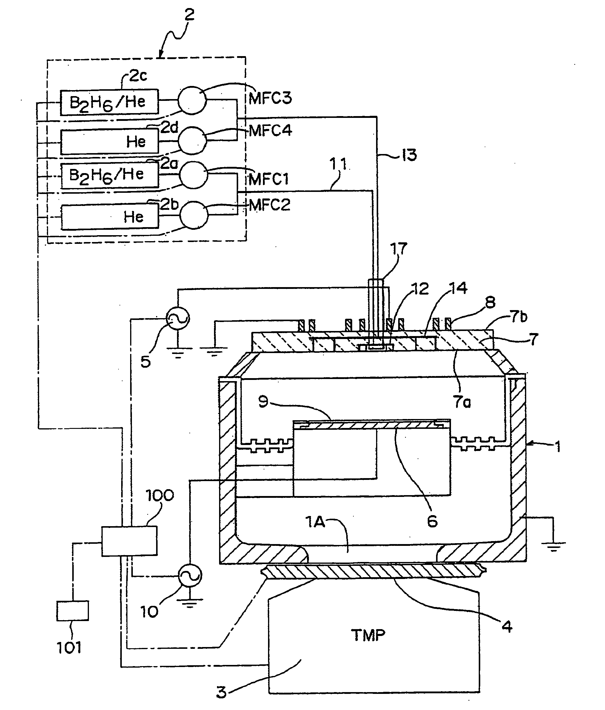
[0222]FIG. 1A shows a partially sectional view of the plasma doping apparatus used in the first embodiment of the present invention. In FIG. 1A, the vacuum vessel 1 is exhausted by a turbo molecular pump 3 as an example of an exhaust device, while introducing a prescribed gas into the vacuum vessel 1 constituting a vacuum chamber from a gas supply device 2, and the inside of the vacuum vessel 1 can be set in a prescribed pressure by a pressure control valve 4. By supplying a high-frequency power of 13.56 MHz to a coil 8 provided in the vicinity of a top plate 7 opposite to a sample electrode 6 from a high-frequency power supply 5, plasma can be generated in the vacuum vessel 1. A silicon substrate 9 is placed on the sample electrode 6, as an example of a sample. In addition, a high-frequency power s...
first modification
(First Modification)
[0274]For example, as shown in FIG. 4A to FIG. 5C, as a first modification, lines 11M, 13M of stainless steel may be directly connected to the central part of the outer surface 7b of the top plate 7. That is, the first gas supply line 11M and the second gas supply line 13M are similarly bent at right angles, and their end portions are respectively directly connected to the central part of the outer surface 7b of the top plate 7. More specifically, each lower end of the first gas supply line 11M and the second gas supply line 13M is fixed to a connection member 25, and two positioning projections 18, 18 are formed on a lower surface of the connection member 25. Meanwhile, two positioning holes 19, 19 are formed in the central part of the outer surface 7b of the top plate 7, and when the first gas supply line 11M and the second gas supply line 13M are directly connected to the central part, the two positioning projections 18, 18 of the connection member 25 are enga...
second modification
(Second Modification)
[0281]Next, as a second modification, instead of providing in the gas flow passage forming member 17 the branched flow passage to the flow passage in the lateral direction from the flow passage in the vertical direction as shown in FIG. 2A, a simplified structure wherein only the flow passage in the vertical direction is formed in a gas flow passage forming member 17N is shown in FIG. 6A to FIG. 7C.
[0282]Specifically, an upper-side vertical gas flow passage 15Na and an upper-side vertical gas flow passage 16Na constituting a part of the first gas flow passage 15 and a part of the second gas flow passage 16 respectively along the longitudinal direction of the gas flow passage forming member 17N are formed in the gas flow passage forming member 17N.
[0283]Meanwhile, a recess portion 7Nc is formed in the central part of the outer surface 7b of the top plate 7 without penetrating therethrough, so as to achieve connection by engagement of an engagement part 17Nb of th...
PUM
| Property | Measurement | Unit |
|---|---|---|
| bias voltage | aaaaa | aaaaa |
| bias voltage | aaaaa | aaaaa |
| diameter | aaaaa | aaaaa |
Abstract
Description
Claims
Application Information
 - R&D
- Intellectual Property
- Life Sciences
- Materials
- Tech Scout
- Unparalleled Data Quality
- Higher Quality Content
- 60% Fewer Hallucinations
Browse by: Latest US Patents, China's latest patents, Technical Efficacy Thesaurus, Application Domain, Technology Topic, Popular Technical Reports.
© 2025 PatSnap. All rights reserved.Legal|Privacy policy|Modern Slavery Act Transparency Statement|Sitemap|About US| Contact US: help@patsnap.com


