
Displacement measuring apparatus

a technology of displacement measurement and measuring apparatus, which is applied in the direction of measuring devices, instruments, and optical conversion of sensor output, etc., can solve the problems of difficulty in further unable to achieve greater precision and higher resolution, and difficulty in reducing the pitch of the magnetic pattern. achieve the effect of greater precision, higher speed and response, and greater precision

Active Publication Date: 2009-02-05
DMG MORI SEIKI CO LTD
View PDF7 Cites 18 Cited by
  • Summary
  • Abstract
  • Description
  • Claims
  • Application Information

AI Technical Summary

Benefits of technology

[0013]Also, in the displacement measuring apparatus of optical type such as disclosed in the Application Publication No. 2006-177876, by reflecting the light diffracted by a diffraction grating and irradiating again the diffraction grating, the pitch of reproduced signals, which are optically detected by photoreceptor element, can be decreased. Therefore, the pitch of the reproduced signals detected optically is considered in general to be approximately from 0.1 to 40 μm, and measurements have been achieved with greater precision and higher resolution. However, in this displacement measuring apparatus of optical type, the greater precision and higher resolution may not be attained when narrowing the pitch of reproduced signals, and hence the speed and response are delayed concomitantly during the measurement of displacement values.
[0014]According to embodiments of the invention, there is provided a displacement measuring apparatus capable of performing measurements of the amount of displacement with higher speed and response and with greater precision and higher resolution.
[0016]In the displacement measuring apparatus according to an embodiment of the present invention, the magnetic detecting unit detects the magnetic field generated by the magnetic pattern and measures an amount of displacement with higher speed and response, and the optical detection unit detects the light diffracted by the diffraction grating and measures the amount of displacement with greater precision and higher resolution.

Problems solved by technology

However, in the displacement measuring apparatus of magnetic type such as disclosed in the Application Publication No. 2002-267493, there gives rise to a difficulty when the pitch of the magnetic pattern is decreased.
Therefore, the pitch of the magnetic pattern (i.e., pitch of reproduced signals detected by the detection element) is considered in general to be approximately from 40 to 5000 μm, and it has been regarded difficult to further decrease the pitch of the magnetic pattern and to thereby achieve greater precision and higher resolution.
However, in this displacement measuring apparatus of optical type, the greater precision and higher resolution may not be attained when narrowing the pitch of reproduced signals, and hence the speed and response are delayed concomitantly during the measurement of displacement values.

Method used


Image

  • Displacement measuring apparatus
  • Displacement measuring apparatus
  • Displacement measuring apparatus

Examples


Embodiment Construction

[0024]The invention will be described hereinbelow on a variety of embodiments of displacement measuring apparatuses by referring to the accompanying drawings. It is not intended to be exhaustive or to limit the invention to those disclosed in the embodiments and illustrated in the drawings.

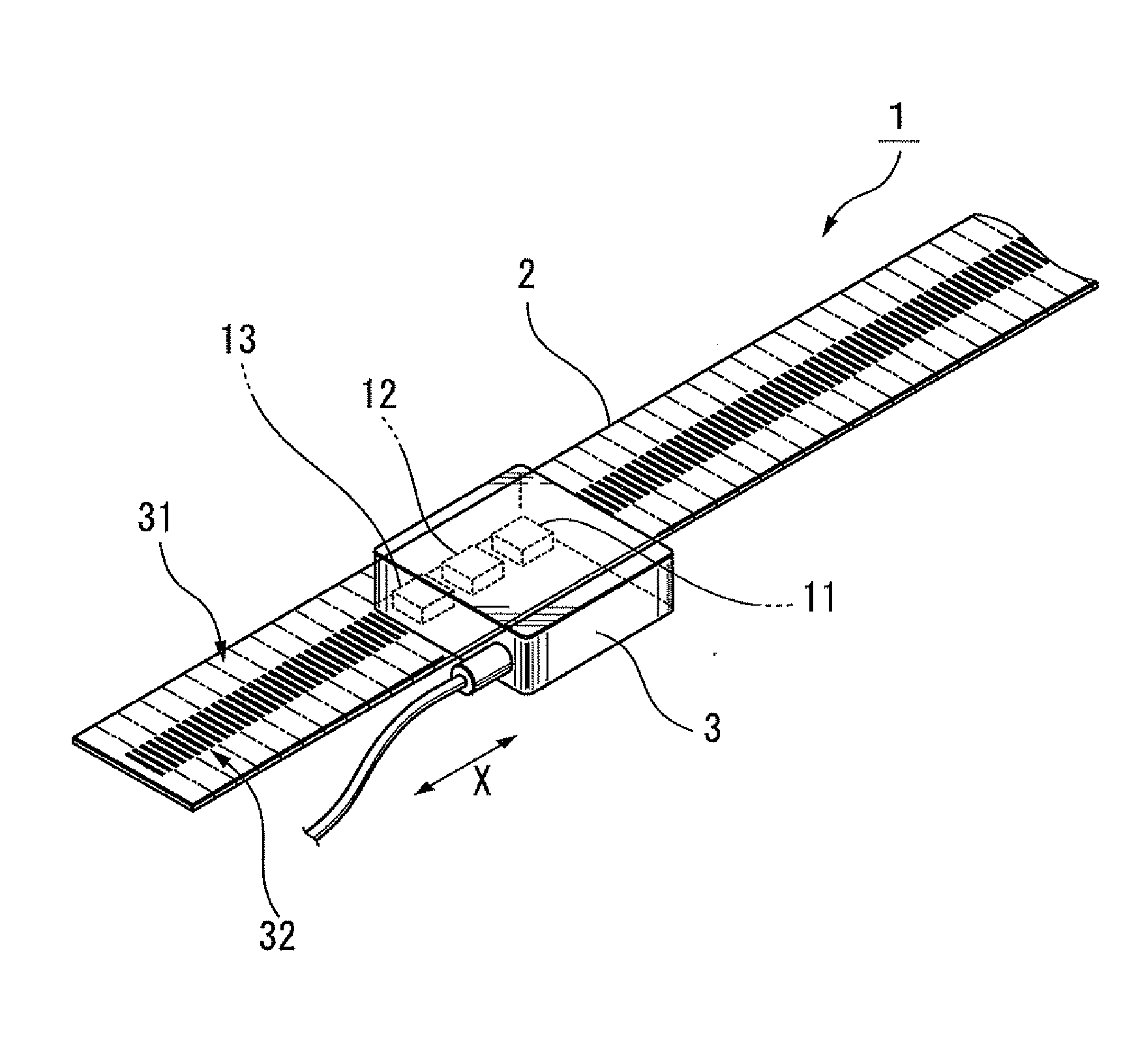
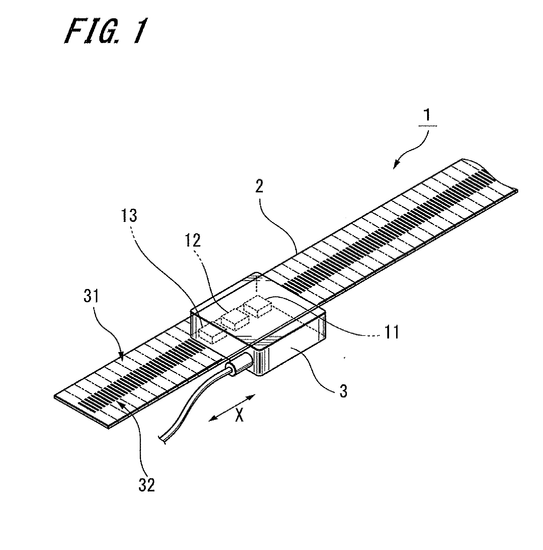
[0025]FIG. 1 is a perspective view illustrating a displacement measuring apparatus according to a first embodiment of the present invention. The displacement measuring apparatus 1 is configured to carry out measurements of linear displacements, namely, as the so-called linear type displacement measuring apparatus.

[0026]Referring to FIG. 1, the displacement measuring apparatus 1 includes at least a composite scale 2 having a magnetic pattern 31 and a diffraction grating 32, each aligned in the direction X of measuring axis (or, hereinafter referred to as “measuring axis direction X”), and a detector head 3 moving in the measuring axis direction X relative to the composite scale 2.

[0027]The detector...


PUM


Abstract

Disclosed is a displacement measuring apparatus that includes a composite scale having a magnetic pattern and a diffraction grating each aligned in a direction of measuring axis, and a detector head moving in a direction of measuring axis relative to the composite scale. The detector head has a magnetic detection unit detecting a magnetic field exerted by the magnetic pattern to generate first reproduced signals, a light source irradiating the diffraction grating with light, and an optical detection unit detecting the light diffracted by the diffraction grating to generate second reproduced signals. In composite scale, the magnetic pattern and the diffraction grating are arranged such that a pitch of the first reproduced signals is larger than that of the second reproduced signals.

Description

CROSS REFERENCES TO RELATED APPLICATIONS[0001]The present invention contains subject matter related to Japanese Patent Application JP 2007-201283 filed in the Japanese Patent Office on Aug. 1, 2007, the entire contents of which being incorporated herein by reference.BACKGROUND OF THE INVENTION[0002]1. Field of the Invention[0003]The invention generally relates to displacement measuring apparatuses. More particularly, the invention relates to a displacement measuring apparatus for use in measurements of linear and rotational displacements.[0004]2. Description of the Related Art[0005]Displacement measuring apparatuses are generally known as the apparatus for implementing precise measurements of linear or rotational displacements, and other similar displacements, which are implemented with a scale and a detector head. The measuring apparatuses have been widely used, for example, in a packaging equipment of electronic components, which generally requires precise positioning control of m...

Claims


Application Information

Patent Timeline
IPC IPC(8): G01B11/02G01B7/14
CPCG01D5/58G01D5/56G01B7/00G01B11/00
Inventor KON, MASAHITOTANIGUCHI, KAYOKOTAMIYA, HIDEAKIONODERA, YASUHIKOTSUCHIYA, HIDEKIKURODA, AKIHIRO
Owner DMG MORI SEIKI CO LTD
Learn More