
Knocking Control System for Gas Engine

a control system and gas engine technology, applied in the direction of electric control, ignition automatic control, instruments, etc., can solve the problems of engine damage, abnormal combustion such as knocking, and achieve the effect of suppressing the occurrence of knocking, and reducing the power output of the cylinder

Active Publication Date: 2011-09-15
KAWASAKI HEAVY IND LTD
View PDF7 Cites 15 Cited by
  • Summary
  • Abstract
  • Description
  • Claims
  • Application Information

AI Technical Summary

Benefits of technology

[0005]Accordingly, an object of the present invention is to provide a control system which has a high control response, is capable of sufficiently suppressing occurrence of knocking and prevents an engine cylinder from being placed under a thermal overload.Solution to Problem
[0013]For example, in a case where control for reducing the power output is executed simultaneously for a plurality of cylinders among all cylinders, there is a possibility that the load increases in the remaining cylinders to achieve a target power output in an overall engine, which may possibly induce knocking in the remaining cylinders. However, in accordance with the above configuration, in a case where the control for reducing the power output is executed simultaneously for a plurality of cylinders which are more than the predetermined number, the power output upper limit value of the gas engine is decreased. Therefore, it is possible to prevent the knocking from being induced in the remaining cylinders, and to prevent these cylinders from being overloaded.

Problems solved by technology

However, in gas engines, abnormal combustion such as knocking may occur during its operation.
A pressure wave generated at the time of self-ignition imposes a burden on the engine, and as a result, the engine could be damaged.

Method used


Image

  • Knocking Control System for Gas Engine
  • Knocking Control System for Gas Engine
  • Knocking Control System for Gas Engine

Examples


Embodiment Construction

[0019]Hereinafter, an embodiment of the present invention will be described with reference to the drawings.

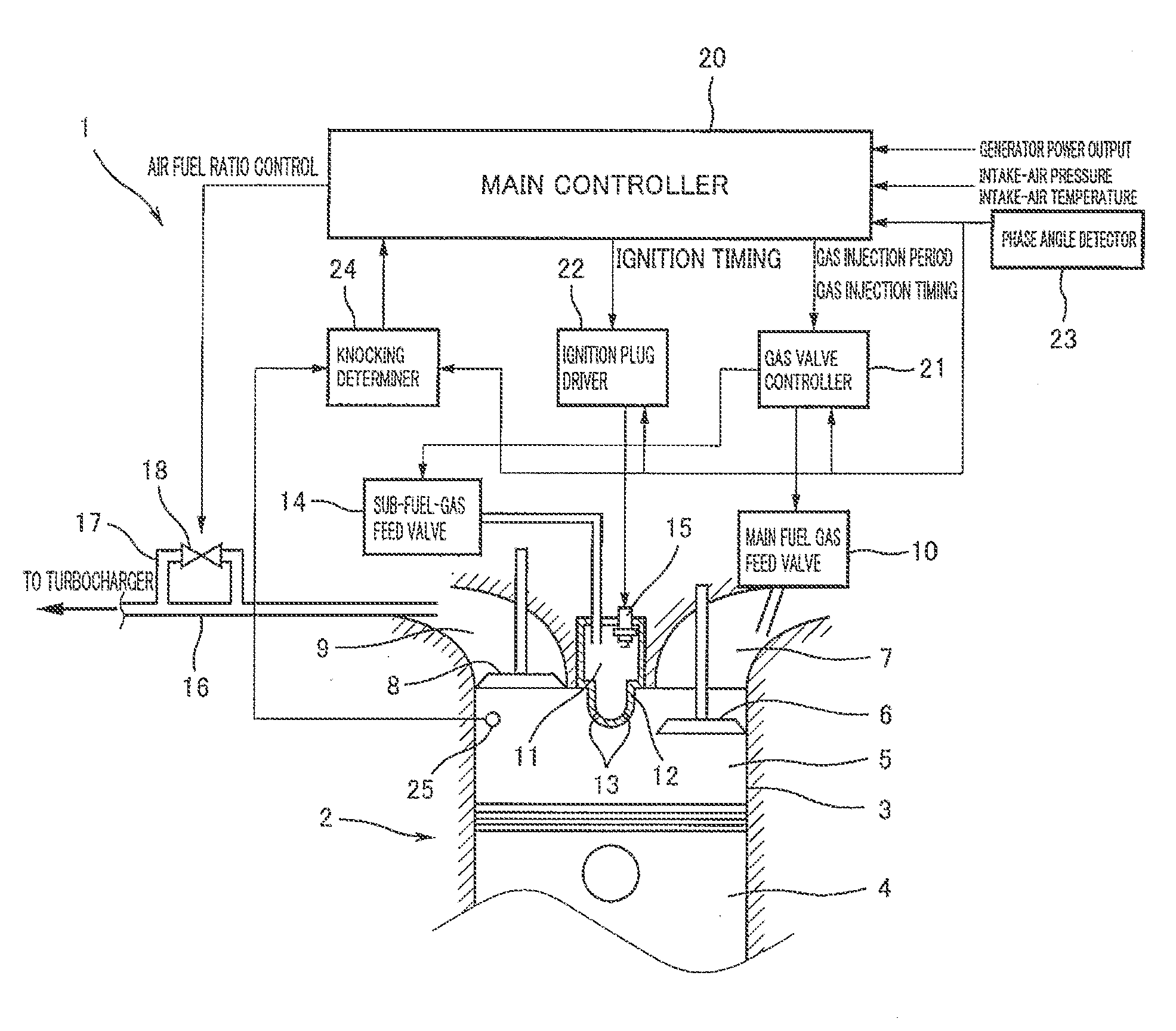
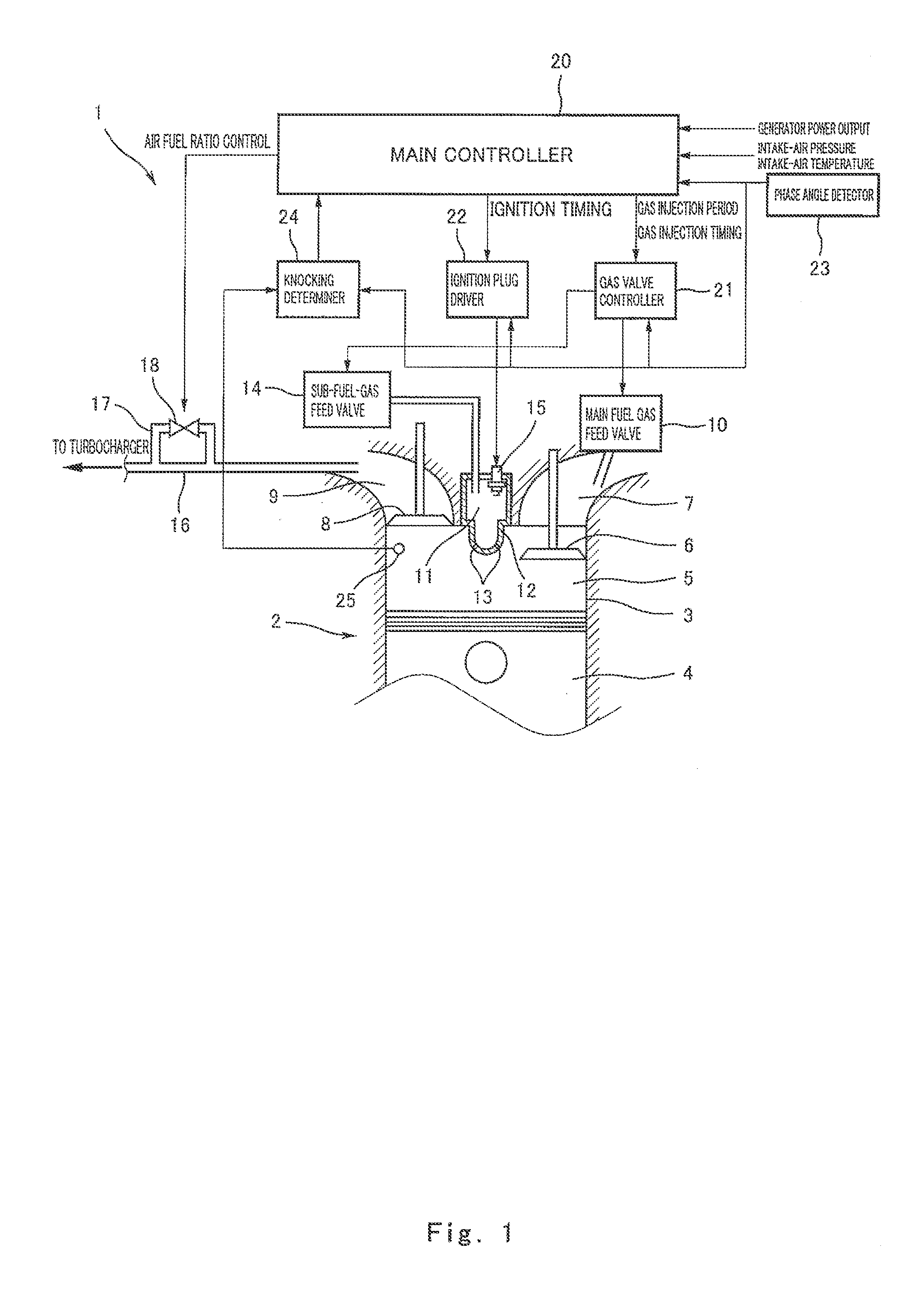
[0020]FIG. 1 is a view showing a configuration of a knocking control system 1 of a gas engine 2 according to an embodiment of the present invention. As shown in FIG. 1, the gas engine 2 is a reciprocating multi-cylinder four-stroke engine which uses as a main fuel a gas fuel such as natural gas, city-supplied gas, etc., and is used as a prime mover of power generation equipment. In FIG. 1, a single cylinder 3 in the gas engine 2 is depicted as a representative example, but other cylinders which are not shown have the same configuration.

[0021]A piston 4 is reciprocatably inserted into the cylinder 3. The piston 4 is coupled to a crankshaft (not shown) which is an output shaft. A main combustion chamber 5 is formed above the piston 4 inside the cylinder 3. An intake port 7 is coupled to the main combustion chamber 5 via intake valve(s) 6, and exhaust port 9 is coupled to the main...


PUM


Abstract

A knocking control system comprises a knocking determiner device for determining whether or not knocking with a predetermined intensity or higher has occurred in a cylinder of a gas engine in each cycle; an integration variable calculator which adds to an integration variable CT when the knocking determiner device determines that the knocking with the predetermined intensity or higher has occurred, and subtracts from the integration variable CT when the knocking determiner determines that the knocking with the predetermined intensity or higher has not occurred; and a main controller for reducing a power output of the cylinder if the integration variable CT is not less than a threshold.

Description

TECHNICAL FIELD[0001]The present invention relates to a knocking control system for a gas engine using a gas fuel such as natural gas, city-supplied gas, etc.BACKGROUND ART[0002]In recent years, in factories, electric power systems have been provided that use both electric power supplied via power lines from a power company, and also electric power generated by a power generator driven by a gas engine installed within the factory. Gas engines have a high energy efficiency when they conduct combustion in a fuel lean state, and are suitable for use in power generation equipment operating with a constant load. However, in gas engines, abnormal combustion such as knocking may occur during its operation. Knocking is a phenomenon in which an uncombusted air-fuel mixture is self-ignited in a combustion stroke and combustion occurs before the flame propagates or the spark timing. A pressure wave generated at the time of self-ignition imposes a burden on the engine, and as a result, the engi...

Claims


Application Information

Patent Timeline
IPC IPC(8): F02D45/00
CPCF02B19/108F02M21/0278F02D35/027F02D41/0027F02P5/045Y02T10/125F02D35/023F02D19/024F02P5/152F02P5/153F02P13/00Y02T10/46Y02T10/32F02M21/0275F02M21/0284F02B19/12Y02T10/12Y02T10/30Y02T10/40F02D19/02F02D45/00F02M21/02
Inventor IMAMURA, TSUKASASUGIMOTO, TOMOHIKOTOKUOKA, TETSUOISHII, HIROYOSHI
Owner KAWASAKI HEAVY IND LTD
Learn More