Metal and oxide interface assembly to sustain high operating temperature and reduce shaling

a technology of metal oxide and interface, applied in the manufacture of electrode systems, electric discharge tubes/lamps, silicon compounds, etc., can solve the problems of compromising performance, physical structure and nature of the electrode-pin assembly, and additional stress during lamp manufacturing

Inactive Publication Date: 2009-02-05
GENERAL ELECTRIC CO
View PDF10 Cites 4 Cited by
  • Summary
  • Abstract
  • Description
  • Claims
  • Application Information

AI Technical Summary

Benefits of technology

[0010]The invention relates to a barrier layer provided on the electrode assembly of a discharge lamp comprising at least a layer of nanoclusters of a non-oxidizing material. Further, the invention relates to an electrode assembly for a discharge lamp comprising an electrode having a foil attached thereto to create an electrode assembly, the assembly being coated with a multi-layer coating comprising at least a layer of non-oxidizing material having a thickness of less than 1 nm and in the form of nanoclusters, and at least another layer of non-oxidizing material, such that the total coating thickness is up to 1500 nm. A method to reduce thermal expansion mismatch between an electrode assembly and a discharge lamp envelope is also provided, the method comprising providing an electrode assembly and depositing on the surface of the assembly a coating having at least a nanoclusters layer of a non-oxidizing material, and subsequently subjecting the lamp envelope in the electrode assembly area to pinching to create a pinch area, this lamp being able to operate at elevated temperature for extended periods, in excess of 1000 hours.

Problems solved by technology

The electrode-pin assembly are by their physical structure and nature fragile.
In addition, they are subject to additional stress during lamp manufacture and during lamp operation, particularly at elevated temperatures.
However, while this does increase the stability of the electrode assembly within the lamp structure, it also generates a potential problem with regard to the glass envelope coming into direct contact with the electrode wire, and compromising the performance thereof.
Even with the addition of the metal foil to the electrode assembly, the lamp continues to experience thermal expansion mismatch problems.
This foil / coil assembly, even though it is intended to provide support for the electrode, may fail for several reasons.
For example, the assembly may fail due to structural weakness, or to continued thermal mismatch of the assembly component materials.
This correlates to a stress point in the structure, which under normal or conventional operating conditions will eventually lead to lamp failure, but which is amplified under high operating temperature conditions resulting in early lamp failure.
For example, under high temperature operating conditions, the pinch portion of the lamp may experience temperatures in excess of 500° C. Because the molybdenum foil oxidizes at around 500° C., within the first 400 hours of operation the foil suffers oxidation-generated degradation which leads to early lamp failure.
Therefore, use of the conventional foil / coil electrode support in extended or long operating lamps, on the average of up to 1000 to 2000 operating hours, is not a viable option.

Method used


Image

  • Metal and oxide interface assembly to sustain high operating temperature and reduce shaling
  • Metal and oxide interface assembly to sustain high operating temperature and reduce shaling
  • Metal and oxide interface assembly to sustain high operating temperature and reduce shaling

Examples


Embodiment Construction

[0015]The invention relates to a coating for deposition on the foil / coil in the pinch area of a discharge lamp. More specifically, the invention relates to a coating that eliminates the problems caused by thermal mismatch between the quartz envelope and the foil / coil support assembly in the pinch portion of A discharge lamp. In addition, the coating has the capability to reduce or hinder the progression of oxidation of the metal foil sufficiently to extend operating life of the lamp to the desired 1000 to 2000 hours.

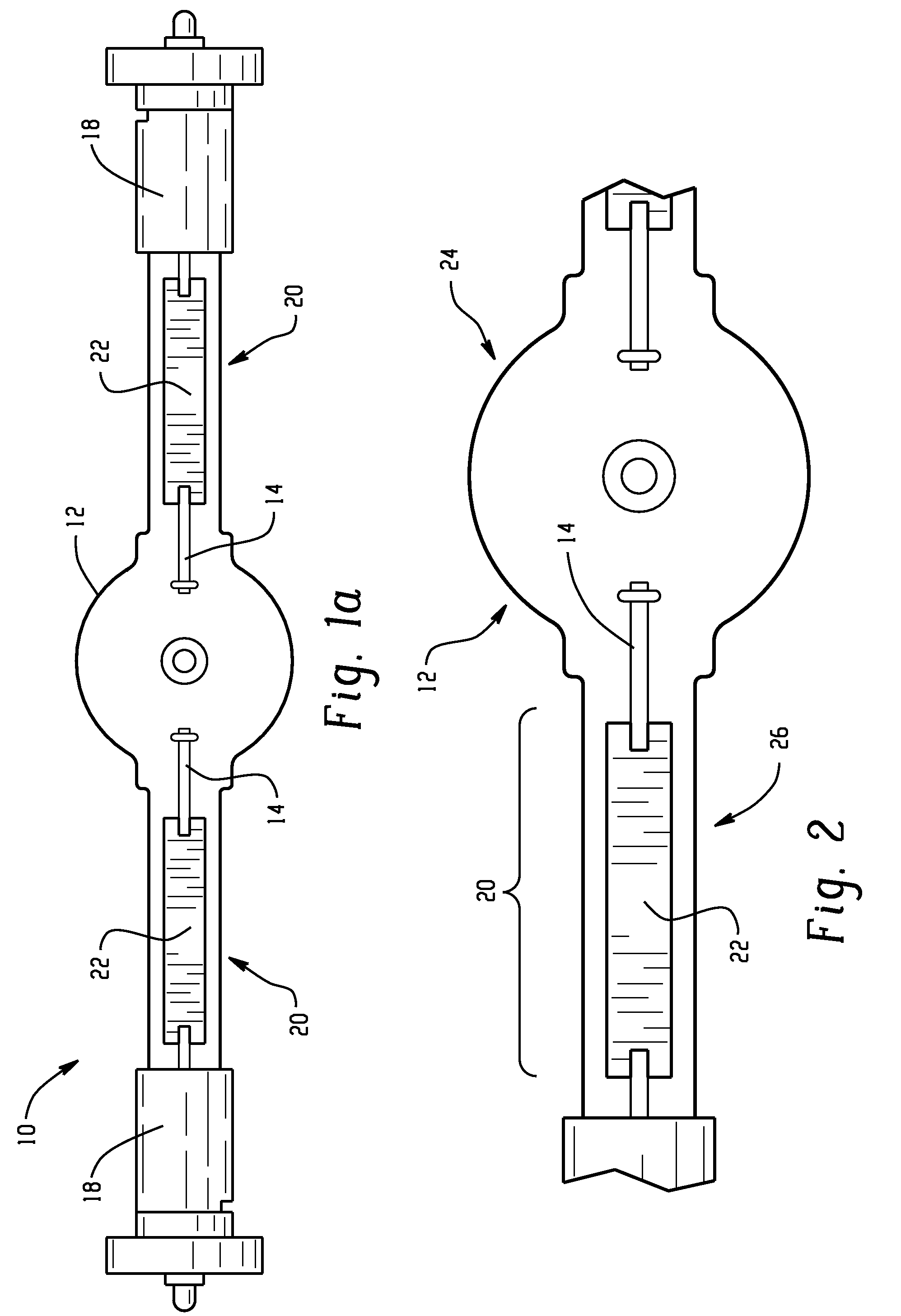
[0016]With reference to FIG. 1 or FIG. 1a, there is shown a representative discharge lamp 10, which is generally known in the art. The lamp 10 has a glass tube or light-transmissive envelope 12 which has a circular cross-section, and would include the conventional electrodes 14, fill gas 16, and mercury components (not shown) known in the art. The tube 12 is hermetically sealed at both ends by bases 18. The electrodes 14 are mounted in the bases 18, such that they sustai...


PUM

PropertyMeasurementUnit
thicknessaaaaaaaaaa
temperatureaaaaaaaaaa
temperaturesaaaaaaaaaa

Abstract

The invention relates to a barrier layer provided on the electrode assembly of a discharge lamp comprising at least a layer of nanoclusters of a non-oxidizing material. Further, the invention relates to an electrode assembly for a discharge lamp comprising an electrode having a foil attached thereto to create an electrode assembly, the assembly being coated with a multi-layer coating comprising at least a layer of non-oxidizing material in the form of nanoclusters, and at least another layer of non-oxidizing material, such that the total coating thickness is up to 1500 nm. A method to reduce thermal expansion mismatch between an electrode assembly and a discharge lamp envelope is also provided, the method comprising providing an electrode assembly and depositing on the surface of the assembly a coating having at least a nanocluster layer of a non-oxidizing material, and subsequently subjecting the lamp envelope in the electrode assembly area to pinching to create a pinch area, this lamp being able to operate at elevated temperature for extended periods, in excess of 1000 hours.

Description

BACKGROUND OF THE INVENTION[0001]The present disclosure relates to discharge lamps. It finds particular application with regard to high intensity quartz or ceramic discharge lamps that operate at elevated temperatures, and to the use therein of a non-oxidizing barrier layer on the foil and / or coil assembly of the lamp, and to devices exhibiting a metal and / or a nonmetal / semiconductor interface. However, it is to be appreciated that the present disclosure will have wide application throughout the lighting and related industries.[0002]Generally known in the art are fluorescent and other discharge lamps. These lamps have a glass tube or light-transmissive envelope, usually with a circular cross-section. This envelope houses the lamp electrodes, a supporting fill gas, and various mercury components known in the art. The envelope may be hermetically sealed at both ends. The lamp electrodes are mounted in one or more bases, usually positioned at the ends of the envelope, these bases also ...

Claims


Application Information

Patent Timeline
Patent Type & Authority Applications(United States)
IPC IPC(8): H01J1/00C01B13/14C01B15/14H01J9/00C01G3/02
CPCH01J61/368H01J61/0732
Inventor AURONGZEB, DEEDER M.
Owner GENERAL ELECTRIC CO
Why Eureka
Try Eureka