
Evacuated Thermal Insulation Panel

a technology of vacuum panels and thermal insulation materials, applied in the direction of thermal insulation improvement, pipe protection by thermal insulation, heat insulation, etc., can solve the problems of increasing the pressure level of the prior art insulating vacuum panels, limiting the effective life of the panel, etc., and achieve the effect of facilitating access

Inactive Publication Date: 2009-02-05
THERMOVAC LTD
View PDF22 Cites 74 Cited by
  • Summary
  • Abstract
  • Description
  • Claims
  • Application Information

AI Technical Summary

Benefits of technology

[0075]More preferably, the evacuated insulation panel of claim 43, further comprising a linking fitting adapted to be connected to the vacuum valve via the suction interface, the linking fitting being adapted to transfer suction pressure between the vacuum valve and a suction apparatus or an adaptor thereof, the linking fitting having an integrated tube operable for facilitating access to the valve stopper.

Problems solved by technology

The aforementioned thermal insulation materials have relatively low thermal conductivity.
In practice, the pressure level of the state of the prior art insulating vacuum panels increases over time, mainly due to penetration of atmospheric gases and water vapor through seams in the panel envelope.
However, the addition of chemical agents increases the production costs Moreover, the chemical agents have a finite effective duration and a finite absorption and adsorption capacity, hence limiting the effective life of a panel based on them.
Thus, if Fumed Silica core materials are sealed in an evacuated panel, the increase in the pressure level in panels will have a relatively minor effect on their low thermal conductivity level, especially in the light of open cell polystyrene foam with typical cell size of 30 microns on average.
However, currently, Fumed Silica materials are relatively expensive, and lack the hardness benefits of other core materials such as Open Cell Foams, which can be used as a rigid skeleton for the structure of insulation panels.
Due to production costs concerns, generally Aluminum films are used.
Clearly, this conduction, which is also known as thermal edge or thermal bridge, can substantially reduce the insulation performance of a panel.
Though the rigid plastic micro-porous sealed-in evacuated container provides a good insulation layer, the WO 98 / 29309 vacuum insulation panels fails to maximize the utility of the insulation potential of the panel.
This failure is an outcome of high thermal conductivity of the outer casing's material which is usually made of films with high thermal conductivity, for example aluminum films and metallized films.
Though films with relatively lower conductivity can solve the conductivity problem, such a use is either expensive or not appropriate from other reasons such as instability, fragility or low warmth durability etc.
The use of nonmetal or metallized materials can decrease the thermal conductivity and the thermal edge effect.
Laminated films that comprise various types of coated and uncoated polymers and metal foils and the combination thereof, which are convenient to make pouches from, do not completely solve the gas permeation problem.
A gas leak from the seam decreases the vacuum level over time, raising the thermal conductivity level of the panel.
As mentioned above, one disadvantage of the state of the art is the difficulty to economically maintain the vacuum for long periods.
However, the absorbents provide only a partial solution since the absorbents are inserted before the panel is sealed or evacuated.
Moreover, since the panel is sealed after insertion, there is no practical way to replace the absorbents, unless re-pumping is performed.
It should be mentioned that the state of the art panels do not currently include any efficient mechanism that facilitates re-evacuation of the insulation panels, either by a pump, or by replacing the atmospheric gas absorbents and water vapors absorbents within the panel.
However, the state of the art does not disclose a panel that can indicate to the layman the pressure level in the insulation panel at any given moment, to facilitate timely re-evacuation of the panel accordingly.
However, since the aforementioned mechanism is exposed to the outer surrounding temperature and humidity it is not sufficiently precise.
Another known problem in the prior art is related to the positioning of the insulation panel within insulation units.
In many situations such a procedure is not feasible, as the overall dimensions are restricted and so increased insulation thickness reduces the usable volume and thus the functionality.
The layer of cured polyurethane is relatively voluminous and reduces the relative effective cooling storage space by increasing the thickness of the walls.

Method used


Image

  • Evacuated Thermal Insulation Panel
  • Evacuated Thermal Insulation Panel
  • Evacuated Thermal Insulation Panel

Examples


Embodiment Construction

[0138]The present embodiments comprise a vacuum thermal insulation panel with low thermal conductivity and features for maintaining the predetermined pressure level range for long periods. In addition, the present embodiments comprise a method for manufacturing of vacuum thermal insulation panels and a method for coupling partition walls to insulation panels in insulation units.

[0139]The principles and operation of an apparatus and method according to the present invention may be better understood with reference to the drawings and accompanying description.

[0140]Before explaining at least one embodiment of the invention in detail, it is to be understood that the invention is not limited in its application to the details of construction and the arrangement of the components set forth in the following description or illustrated in the drawings. The invention is capable of other embodiments or of being practiced or carried out in various ways. Also, it is to be understood that the phra...


PUM


Abstract

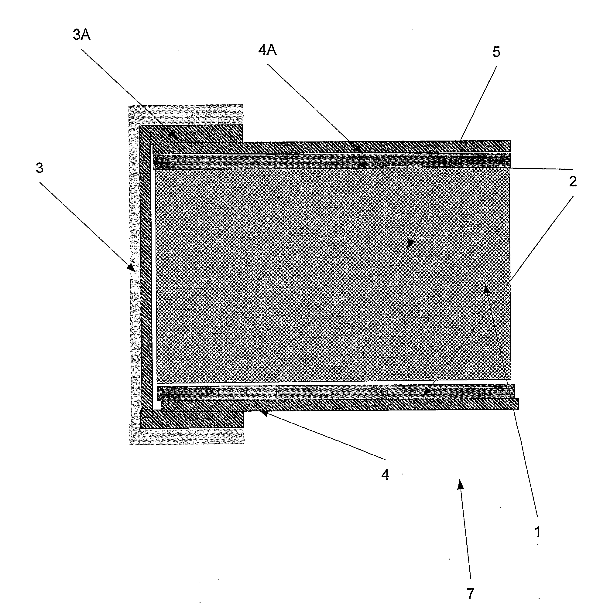
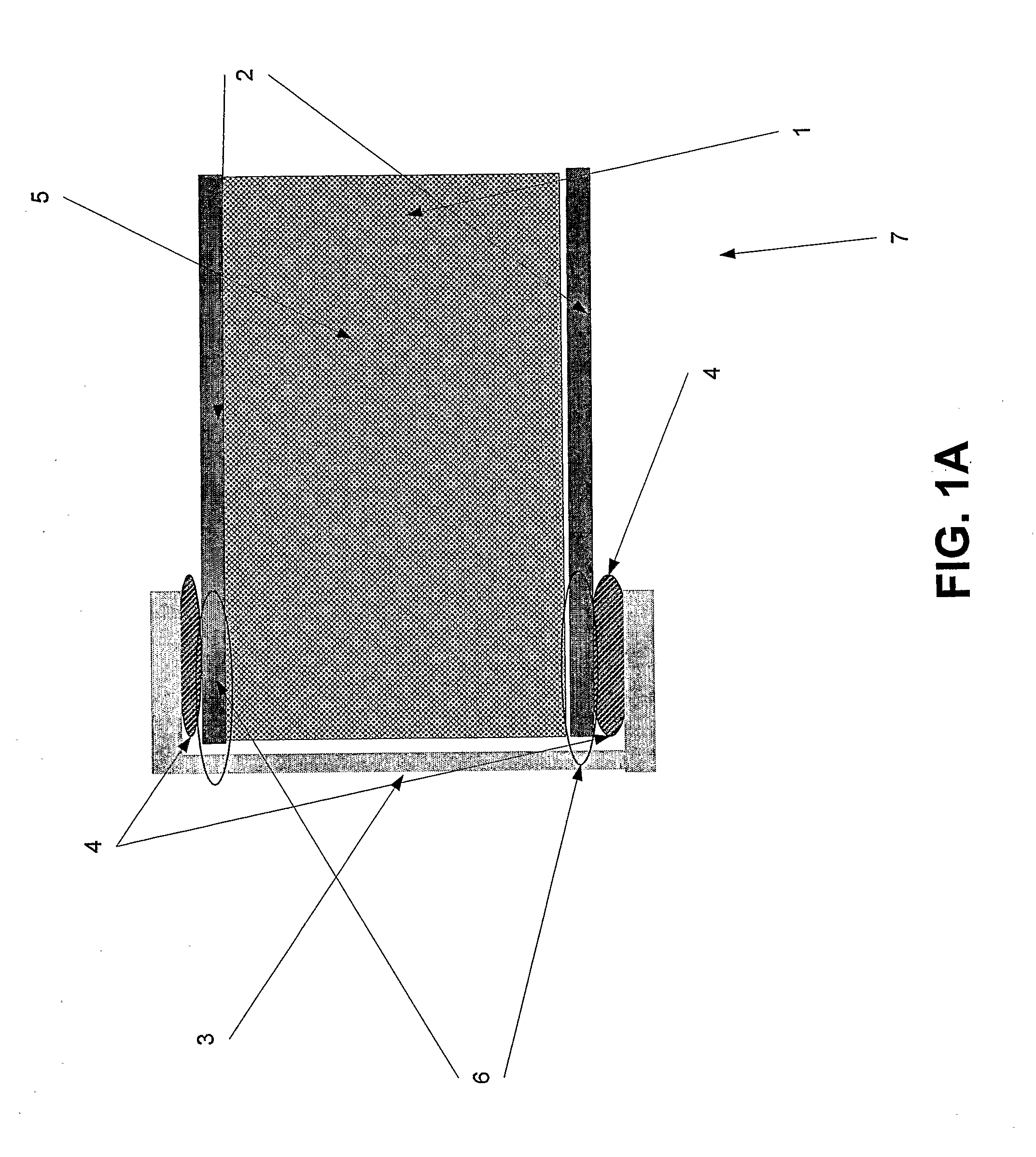
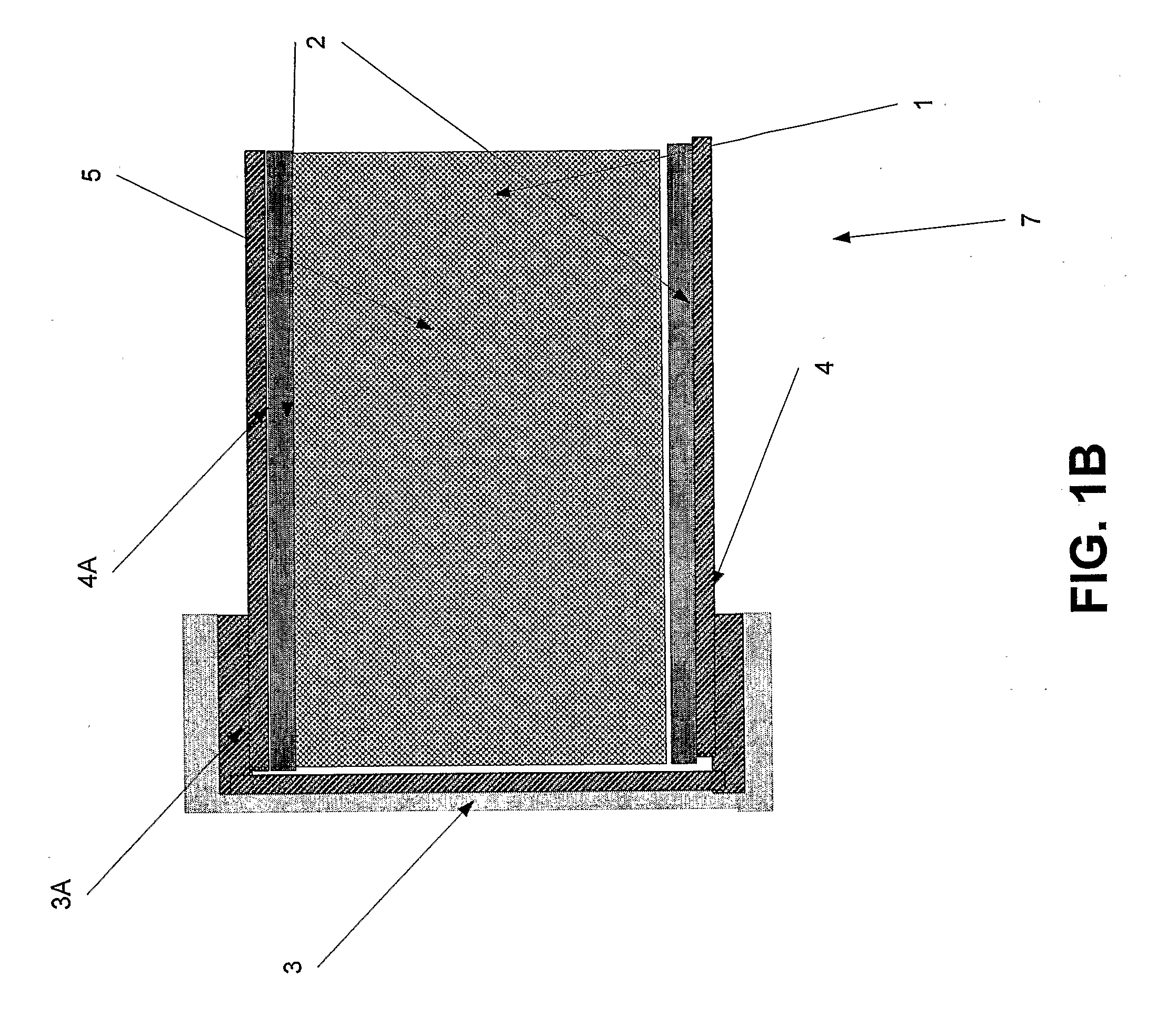
A sealed vacuum thermal insulation panel having a thermal barrier that comprises a core made of thermal insulation material and two panel walls made of a barrier material substantially impermeable to atmospheric gases and water vapors. The two panel walls covers opposite sides of the core. The sealed panel further comprises at least one lateral strip of substantially impermeable to atmospheric gases and water vapor. The lateral strip is adapted to sealably enfold the edges of the obverse side of the two panel walls. Additionally, the sealed panel further comprises at least one sealing strip, each comprising sealing material. The sealing strip is adapted to sealably join the edges to the inner side of the lateral strip.

Description

FIELD AND BACKGROUND OF THE INVENTION[0001]The present invention relates to vacuum thermal insulation panels and to methods to manufacture them, and more particular but not exclusively to a vacuum thermal insulation panel with low conductivity and utilities for maintaining the predetermined pressure level for long periods and a method for bonding panels to insulation unit walls.[0002]Effective thermal insulation is required in a wide range of areas. For example, thermal insulation is a necessity in the transportation of refrigerated products refrigerated containers and spaces, in transportation boxes, in refrigerators and freezers, in cold storage rooms, in refrigerated transport vehicles, buildings, and hot water storage units.[0003]The thermal insulation is a barrier that minimizes the transfer of heat from the outer surrounding to an insulated space and vise versa, by reducing the conduction, the convection and the radiation effects. Hence, the thermal insulation level of any ins...

Claims


Application Information

Patent Timeline
IPC IPC(8): B32B3/12
CPCE04B1/803F16L59/065F25D2201/14Y10T403/18H05K7/20Y02B80/12H05K5/0213Y02A30/242Y10T137/7837Y02B80/10H05K5/0209E04B1/80B32B3/00B82Y30/00
Inventor KALFON, RAMI ABRAHAM
Owner THERMOVAC LTD
Learn More