
Method of Manufacturing Rimless Spectacles and a Mask Suited for Use with said Method

a technology of rimless spectacles and masks, which is applied in the direction of spectacles/goggles, grinding machines, instruments, etc., can solve the problems of spectacle lens breakage, large rejection, through-hole formation in the lens,

Inactive Publication Date: 2009-01-29
MITTERAUER TOBIAS +1
View PDF5 Cites 11 Cited by
  • Summary
  • Abstract
  • Description
  • Claims
  • Application Information

AI Technical Summary

Benefits of technology

[0011]The method according to the invention has the fundamental advantage that in the lenses no holes, either through holes or blind holes, or recesses are formed. This avoids the drawbacks that would be caused by drilling or milling the lenses so as to form holes or recesses. As the lenses are neither drilled nor milled, no breakage of the lenses by drilling or milling and corresponding rejects during spectacles manufacture can take place. For the same reason, in the lenses no tensions are induced which might result in breakage of the glass during use of the spectacles. The lenses of the rimless spectacles manufactured according to the invention are free of tensions.
[0012]Furthermore, the method according to the invention has the advantage that spectacles having coated lenses can be manufactured according to this method. Coating of the lenses is common today in order to provide the surfaces of the lenses with desired properties such as e.g. dirt-repellent properties and scratch resistance. This means that despite adhesively bonding the fasteners to the front side or the rear side of the lenses, which is advantageous for the reasons discussed hereinafter, it is not necessary to do without coating of the lenses.
[0015]It can be provided in an advantageous configuration of the invention that the coating is removed by means of a face grinding tool that performs a high-frequency rotation or reciprocating movement in contact with the front or rear side of the lens at a frequency within the range of from 15 to 40 kHz, preferably within the range of from 24 to 30 kHz. It has been found that, when the coating is abraded in this way, the grinding operation can be easily restricted to the abrasion of the usually very thin coating and that the basic material of the lenses is exposed without tensions being produced in the lens.
[0016]In an advantageous configuration of the method according to the invention furthermore a mask can be used as auxiliary means when removing the coating to form a respective joining surface at the lens, the mask having an opening whose perimeter corresponds at least partly to the perimeter of the joining surface of a respective fastener. This mask is detachably fixed at the lens in such manner that its opening is provided at the mounting position for the fastener and there delimits the joining surface subject to be formed at the lens. Then the coating is abraded by machining of the front or rear side of the lens in the area delimited by the opening of the mask. Thus the mask determines by its opening in which area at the lens the coating has to be removed to form the joining surface at the same and prevents the coating from being removed outside said area. This renders it especially possible to remove the coating for forming the joining surface at the lens manually, i.e. by means of a tool held and guided by an operating person.
[0017]It may be provided in another advantageous configuration of the method according to the invention that the mask does not only serve, during removal of the coating at the lens, for delimiting by its opening the area in which the coating is removed, but further serves as positioning aid for adhesively bonding the fastener to the respective lens. The fastener is adhesively bonded to the lens, while the mask is still detachably fixed at the lens, wherein the fastener is attached to the lens in the area delimited by the opening of the mask fixed at the lens and is adhesively bonded to the same in the thus given relative position with respect to the lens. The edge of the opening is visible and reveals where the fastener has to be attached, during attachment guides the fastener into the opening, and prevents the fastener from getting out of place during setting of the adhesive used for bonding.
[0018]In an advantageous configuration of the method according to the invention it may further be provided that each of the lugs and the bridge are manufactured of a basic body and the fastener or fasteners, wherein the fasteners are made of flexible plastic material of low hardness and the basic body is made of a material different from that of the fasteners. This permits to manufacture the basic body of a material, including metal, sufficiently tight as regards the mechanical stresses of the spectacles and to impart to the fasteners a buffer function which protects the adhesive layer between the joining surfaces against impact loads.

Problems solved by technology

These known ways of connection have the drawback that through-holes have to be formed in the lenses.
When forming the through-holes by drilling or milling, for instance, there is the risk that the spectacle lens breaks, which results in considerable rejects during manufacture of such rimless spectacles.
Furthermore, the through-holes cause tensions in the spectacle lenses which entail an increased risk of breakage during use of the spectacles.
Previous efforts to manufacture rimless spectacles by adhesively bonding the lugs and the bridge to the front or rear side of the lenses have not been successful, because no permanently tight adhesively bonded joints could be obtained and the adhesively bonded joints frequently broke.

Method used


Image

  • Method of Manufacturing Rimless Spectacles and a Mask Suited for Use with said Method
  • Method of Manufacturing Rimless Spectacles and a Mask Suited for Use with said Method
  • Method of Manufacturing Rimless Spectacles and a Mask Suited for Use with said Method

Examples


first embodiment

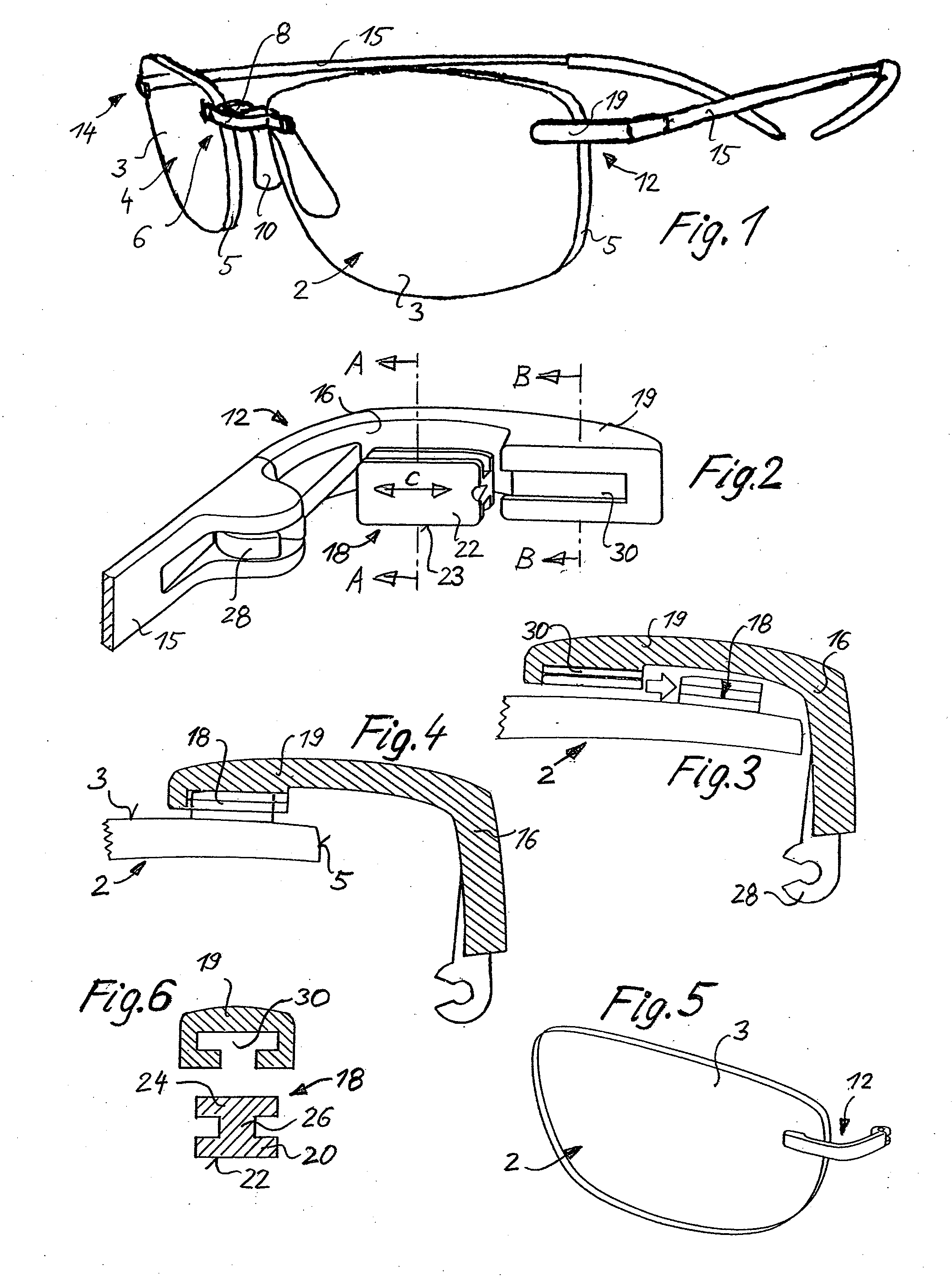
[0049]Hereinafter at first by way of FIGS. 1 to 6 rimless spectacles manufactured according to the invention shall be illustrated.

[0050]FIG. 1 shows these spectacles in perspective view obliquely from the front. The spectacles comprise a left-hand lens 2, a right-hand lens 4 and a bridge 6 disposed between the two lenses.

[0051]Each of the two spectacle lenses 2 and 4 has a front side 3 visible in FIG. 1, a rear side not visible in FIG. 1 and a circumferential edge 5 which delimits the lens radially outwardly with respect to its geometrical and optical centers. The bridge 6 is an elongated element disposed between the two lenses 2 and 4 and interconnecting the latter. The bridge 6 consists of a body 8 and two fasteners not shown in FIG. 1, each of which is disposed at one end of the bridge 6 and is bonded to the front side 3 of the lens 2 and 4, respectively, visible in FIG. 1. A pad member 10 is mounted to the bridge 6 and serves for supporting the spectacles at the nose of the wear...

second embodiment

[0089]In this second embodiment the fastener 18 comprises the projection 66 which encompasses the edge 5 of the spectacle lens 2. The fastener 18 is not only adhesively bonded at its base area 22 to the front side 3 of the lens 2 but is also adhesively bonded at the inside 70 of the projection 66 to the edge 5. However, this is merely an additional adhesively bonding the joining surfaces of which are substantially smaller than the joining surfaces on the front side 3 of the lens 2. In order to permit this additional adhesive bonding it is not necessary to remove a coating at the edge 5 of the lens, because there the base material of the spectacle lens is exposed anyway after forming the lens shape.

third embodiment

[0090]In the third embodiment according to FIGS. 17 to 20 the body 16 of the lug is a component made of metal having the configuration shown in FIG. 17. The body 16 of the lug consists of two curved rods 72 which are parallel to each other and at their one ends are merged into each other forming the charniere 28 and are firmly connected to an oval plate 74 at their other ends.

[0091]The fastener 18 of the third embodiment is an injection-molded plastic member having an oval base area and an arched surface so that in total it has the shape of an oval lens. The fastener 18 is adhesively bonded at its base area to the front side 3 of the lens 2 and includes a slit 76 extending substantially in parallel to its base area. The shape and the dimensions of the slit 76 are adapted to the shape and the dimensions of the plate 74 and to the ends of the rods 72 connected thereto in such way that the plate 74 can be inserted in the slit 76 so that the relative arrangement of the fastener 18 and t...


PUM


Abstract

The invention relates to a method of manufacturing rimless spectacles in which fasteners of the lugs and the bridge of the spectacles are adhesively bonded to the front side or the rear side of the lenses. In the method first of all two lens blanks are manufactured of a plastic material to the front and rear side of which a coating is applied. The two coated lens blanks are cut and ground in a way that two lenses having a desired lens shape are obtained. At predetermined mounting positions for the fasteners of the lugs and the bridge on the front or rear side of the lenses the coating is removed so as to form joining surfaces which substantially correspond to the joining surfaces of the fasteners as to shape and dimensions. The fasteners are then adhesively bonded to the front side and / or to the rear side of the lenses at the mounting positions. Since in the area of the joining surfaces at the lenses the base material thereof is exposed, a permanently firm adhesively bonded joint can be produced between the fasteners and the lenses on the front or rear side thereof using adhesives known per se.

Description

FIELD OF THE INVENTION[0001]The invention relates to a method of manufacturing rimless spectacles and a mask for use in said method.BACKGROUND OF THE INVENTION[0002]Rimless spectacles comprise two spectacle lenses and a bridge disposed between the two lenses and connected thereto, the bridge holding pads or a saddle bridge or is formed integrally with the saddle bridge or the pads. Furthermore rimless spectacles comprise two lugs each of which is connected to either of the two spectacle lenses at a marginal portion of the lens facing away from the bridge and two sides each of which is hingedly connected to either of the lugs. Such rimless spectacles have no mount members extending along the upper edges and / or the lower edges of the spectacle lenses and connecting the bridge to the two lugs. Rather, the coherence between the lugs and the bridge is ensured by the lenses disposed there between. Therefore it is necessary to mechanically connect the lugs and the bridge to the spectacle l...

Claims


Application Information

Patent Timeline
Patent Type & Authority Applications(United States)
IPC IPC(8): G02C13/00B24B13/06
CPCG02C1/023G02C13/001G02C5/00
Inventor ANGER, WILHELMREIKERSTORFER, HERBERT
Owner MITTERAUER TOBIAS
Learn More