
Seat belt apparatus

a seat belt and belt locking technology, applied in the direction of safety belts, pedestrian/occupant safety arrangements, vehicular safety arrangements, etc., can solve the problems of belt locking having to be released, overheating or overloading of motors, and dangerous reactions of occupants

Inactive Publication Date: 2009-01-29
AUTOLIV DEV AB
View PDF12 Cites 5 Cited by
  • Summary
  • Abstract
  • Description
  • Claims
  • Application Information

AI Technical Summary

Benefits of technology

[0006]In accordance with an embodiment of the invention, a unidirectionally effective blocking member is integrated into the powertrain between the drive and the retractor and, starting from a normal blocking state, increases the blocking effect with a force transmission starting from the belt and reverses it into a release state with a force transmission starting from the drive.
[0008]The drive can cancel the blocking of the powertrain using a minimal expenditure of energy and drive the belt retractor with the blocking member in the release state by the possibility of reversing the blocking member between the normal blocking state and the release state.
[0009]In particular in connection with an intelligent control for an electric motor serving as a drive, the electrical energy requirements, and so the required electrical power, can be reduced to a minimum due to the blocking member. It is in particular thereby possible to use the whole system faster and at a higher frequency than before without an overload or overheating of the drive motor occurring.
[0010]The second stroke problem initially explained is also avoided by the invention since the drive for the belt retractor can be used both for the pre-tensioning or pre-tightening of the belt and for the driving of the belt retractor in the reverse direction, that is to unwind the belt. When unwinding the belt, the time development of the belt relaxation can take place directly in accordance with a pre-settable scheme, in particular a scheme which does not disturb the vehicle occupants, in particular advantageous when an electric motor is used.
[0013]In this connection, the blocking member can be arranged between the drive and the mechanical energy store. The blocking member makes it possible to hold the mechanical energy store—for example a tensioned spring—in the filled (or tensioned) state for an unlimited time without a holding torque to be applied by the drive being necessary for this purpose.
[0021]The unidirectional effect of the blocking member can be achieved by a skillful arrangement of its control sections and of the drive sections on the belt side and drive side with which the blocking spring is charged via its control sections.

Problems solved by technology

It is a problem here that these belt systems should be resettable, since the belt has to be relaxed again if the expected impact does not take place or an all-clear signal is given.
If an electric motor is used for the drive of the belt retractor, the problem exists that the motor has to be switched on permanently to hold the pre-tensioned belt, which can result in an overheating or overloading of the motor.
However, it is now a problem that the belt locking has to be released for the mentioned relaxing of the belt on the non-occurrence of the expected impact or accident or on the all-clear signal, which requires, as is known, a second pulling on the belt.
The second pulling on the belt—known as the “second stroke” problem—is not only felt to be irritating by the affected occupant, but can also result in dangerous reactions of the occupant, since the “second stroke” takes place surprisingly for the occupant without a danger situation recognizable by him.
However, the relatively large friction losses of a mechanical holding device based on the principle of friction locking are problematic in this arrangement.
The friction losses have to be balanced via the electric motor, i.e. have to be “added to” the system, which has the consequence of increased energy requirements and a larger electrical power.
This can in turn result in problems with an overheating or overloading of the motor.

Method used


Image

  • Seat belt apparatus
  • Seat belt apparatus
  • Seat belt apparatus

Examples


Embodiment Construction

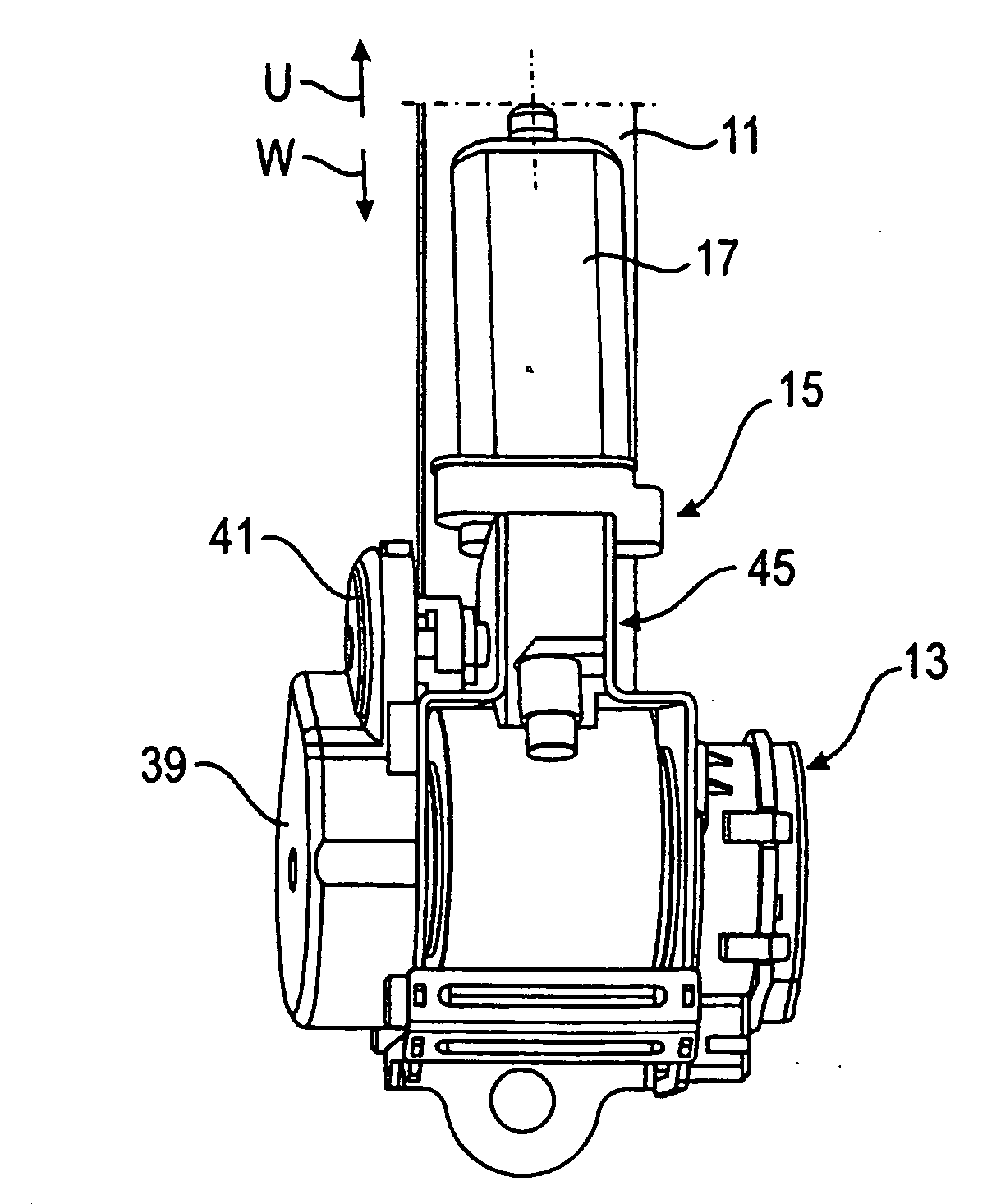
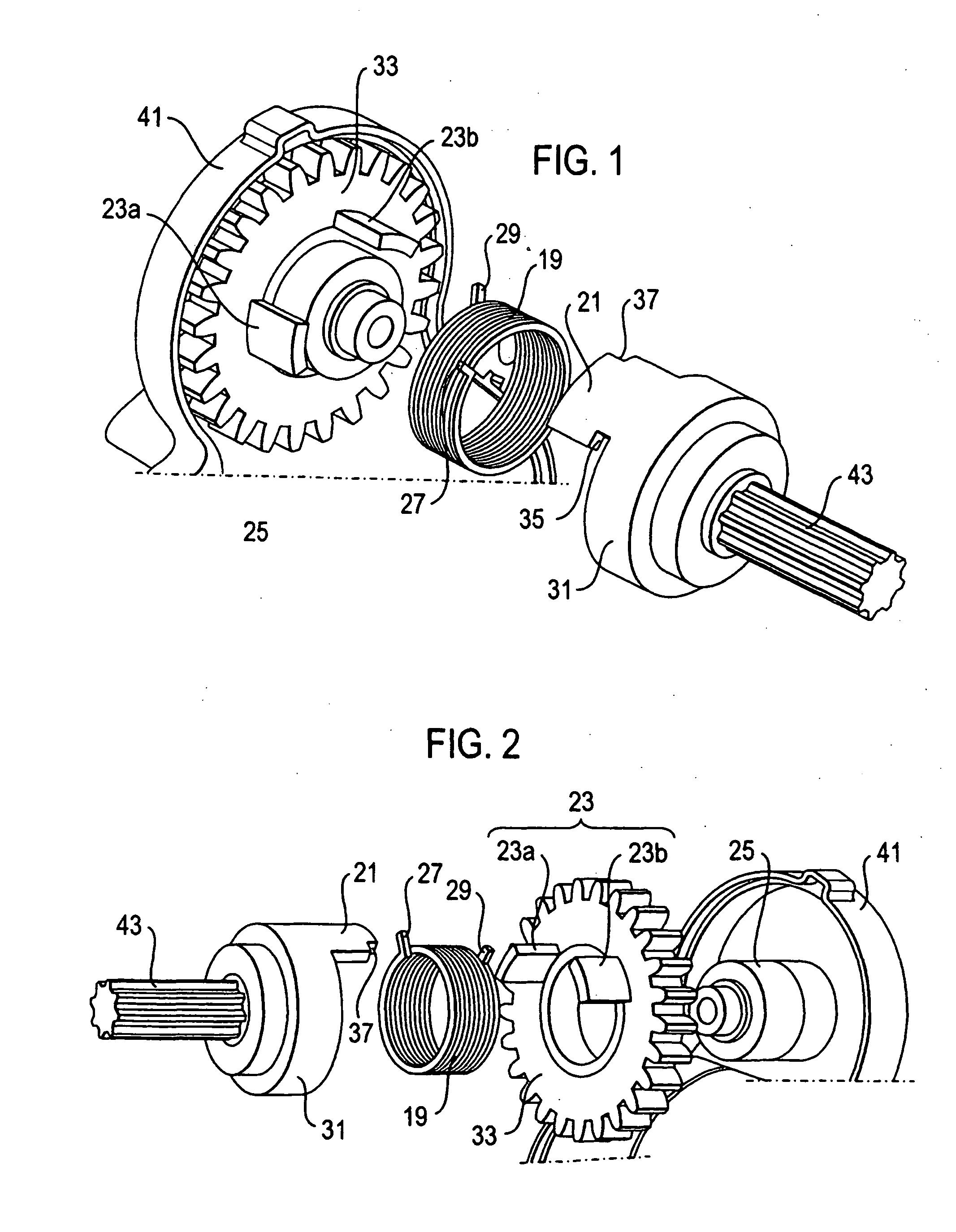
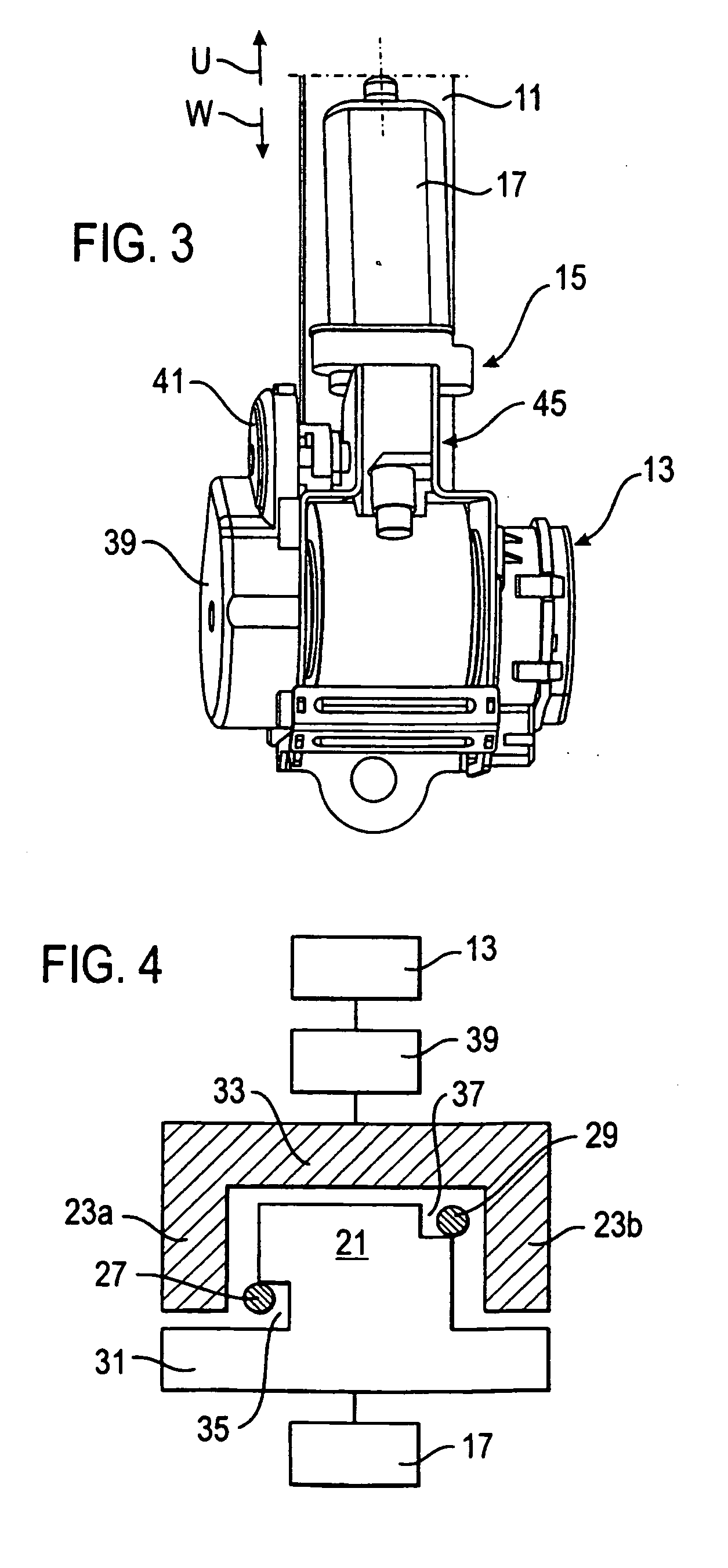
[0032]There are visible of the powertrain in FIGS. 1 and 2—between the drive 15 (FIG. 3), comprising an electric motor 17, on the one hand, and the belt retractor 13, on the other side—on the motor side, a drive shaft 43 having a rotationally fixedly connected support 31 for a drive section 21 on the motor side and, at the belt side, a toothed wheel 33 which is arranged in a housing 41 and which serves as a carrier for a drive section 23 on the belt side which is divided into two parts and which comprises two components 23a, 23b spaced apart in the peripheral direction.

[0033]The drive sections 21, 23 are made as axial projections which are arranged at a radial spacing from a rotary axis which coincide with the central axes of the drive shaft 43 and of a spigot 25 fixed to the housing. The support toothed wheel 33 at the belt side is rotatably supported on the cylindrical spigot 25.

[0034]In the assembled state (FIG. 3, FIG. 4), the drive section 21 on the motor side is located betwee...


PUM


Abstract

The invention relates to a seat belt apparatus for motor vehicles comprising a seat belt, a belt retractor and a drive, which preferably comprises an electric motor, for the retractor, wherein a unidirectionally effective blocking member is integrated into the powertrain between the drive and the retractor which, starting from a normal blocking state, amplifies the blocking effect with a force transmission starting from the belt and reverses it into a release state with a force transmission starting from the drive.

Description

TECHNICAL FIELD OF INVENTION[0001]The invention relates to a seat belt apparatus for motor vehicles comprising a seat belt, a belt retractor and a drive for the retractor.BACKGROUND OF INVENTION[0002]Seat belt apparatuses of this kind are generally known. For example, a so-called pre-safe function or pre-crash function can be realized by means of the drive in that e.g., in the event of an accident, directly before the impact of the vehicle on an obstacle, or due to a warning signal which generates a warning function implemented in the vehicle e.g. by a permanent evaluation and assessment of the traffic situation on the occurrence of a dangerous situation satisfying specific pre-settable conditions, the retractor is driven in the wind-up direction in order to ensure that the belt tightly contacts the body of the respective vehicle occupant in good time. It is a problem here that these belt systems should be resettable, since the belt has to be relaxed again if the expected impact doe...

Claims


Application Information

Patent Timeline
IPC IPC(8): B60R22/34B60R21/00B60R22/46
CPCB60R22/44B60R22/46B60R2022/468B60R2022/4666B60R2022/4473B60R22/26B60R22/12B60R22/38
Inventor ADOMEIT, JULIUSMARSHALL, STEVE
Owner AUTOLIV DEV AB
Learn More