
Cell Aggregation and Encapsulation Device and Method

a cell culture and cell technology, applied in the field of cell culture aggregation and encapsulation devices and methods, can solve the problems of unable to scale up the technique, unable to replenish or change the composition of the culture medium or add new cells to the aggregates in the hanging drops, and hampered the laboratory study of cells and groups of cells

Active Publication Date: 2009-01-15
BROWN UNIVERSITY
View PDF5 Cites 57 Cited by
  • Summary
  • Abstract
  • Description
  • Claims
  • Application Information

AI Technical Summary

Benefits of technology

The patent describes a device that can cause cells to aggregate without using any external force or modifying the surface of the device. The device has a hydrogel substrate with cell-repellant compartments that funnel cells into a minimum of gravitational energy, promoting cell-cell contact and minimizing cell adhesion to the substrate. The device can be used to encapsulate cells and has programmed characteristics and dynamics that can be modified by changing the shape of the aggregation structure or adding aggregation modification agents. The device can be used in cell and tissue engineering for the controlled formation of cell aggregates.

Problems solved by technology

The laboratory study of cells and groups of cells has been hampered by the inability to reproduce the cell's native environment on the benchtop.
The disadvantage of the hanging drop technique is that scaling up the technique has been unsuccessful due to the difficulty of handling large numbers of drops in parallel (i.e. in an array) and the small volumes necessitated.
Another disadvantage is that it is difficult to replenish or change the composition of the culture medium or add new cells to the aggregates in these hanging drops.
Top-loading, in which a defined volume of liquid is applied to a base from above and then turned over causing the drop to hang, has improved the method somewhat but not solved the array issue so the technique is still highly labor intensive.
The appropriate speed of mixing conducive to the formation of aggregates must be experimentally determined: if it is too fast, the cells may be damaged or the aggregates may become excessively large.
Further, the size of the resulting cell aggregates is uncontrollable and variable, and results rarely reproducible.
Moreover, cells are subjected to significant shear forces during the mixing process.
Also cells with relatively weak intercellular adhesion may not readily form aggregates in this high shear environment.
Ordered arrays of aggregates cannot be made because the cells are randomly dispersed within the viscous gel-like methyl cellulose or the gelled soft agar.
The method is not generally applicable to cell aggregation; it is in essence a cell suspension technique as aggregation will not result for a wide variety of cell types and is limited to those cells that actively proliferate under these particular circumstances.
There are many types of hydrogels and most are suitable for some purposes and not suitable for other purposes.

Method used


Image

  • Cell Aggregation and Encapsulation Device and Method
  • Cell Aggregation and Encapsulation Device and Method
  • Cell Aggregation and Encapsulation Device and Method

Examples


example 1

Cell Aggregation Device Fabrication and Cell Culture Preparation

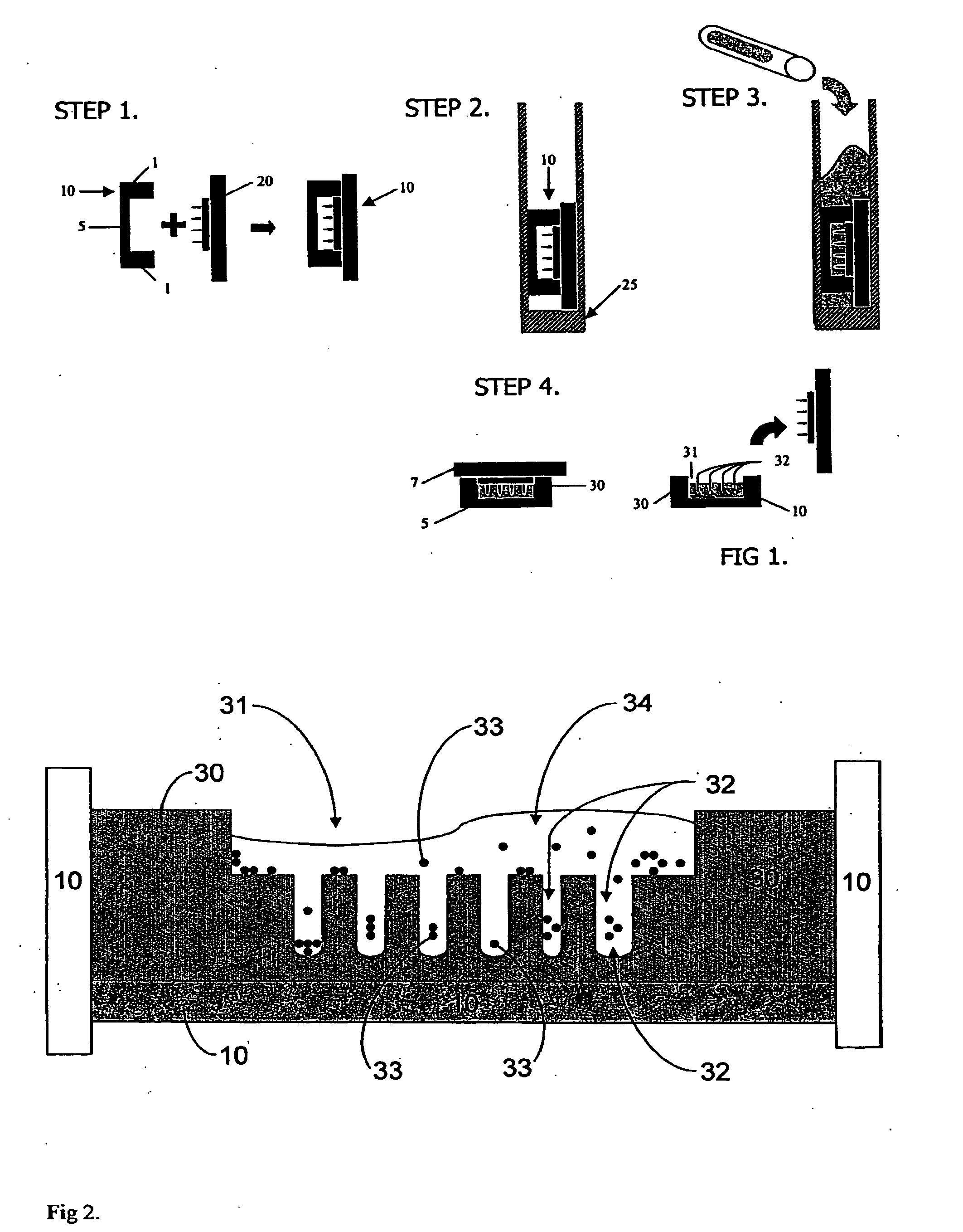
[0081]The fabrication method is illustrated for a general device of the invention in FIG. 1. Thirty millimeter Millicell® CM cell culture inserts 10 (Millipore), which are essentially rigid plastic rings 1 having porous polytetrafluoroethylene (PTFE) membranes 5 on their bottoms, were employed as mold templates. The PTFE membrane, which is transparent when wet, permits diffusion of culture media and visualization of cell aggregates through an inverted microscope. AutoCAD 2005® software was employed to design the shape and contours of various cell aggregation devices and polyacrylamine substrates were made from the wax templates by rapid prototype printing of sequential layers of wax to create the desired 3D CAD designed topography. Mold topography was designed such that gravitational force could funnel cells into the aggregation wells. The wax template was designed to produce a flat square recess 1 mm in depth from the ...

example 2

Cell Seeding and Aggregation of Human Diploid Fibroblasts

[0085]3 ml of cell culture media (DMEM supplemented with 1% penicillin / streptomycin as antibiotic, with and without fetal bovine serum) was added to and the plates transferred to a cell culture incubator and allowed to equilibrate overnight to rinse out any unreacted monomer, neutralize pH and fill the pores of device 30 with the media. In a biological safety cabinet, excess media was aspirated out of the 6-well tissue culture plates. Normal human diploid fibroblast cells were trypsinized, counted and resuspended to a cell density of 1.67 million cells per ml. 300 μl (i.e., about 500,000 cells) were pipetted into each seeding chamber. FIG. 2 illustrates the cells 33, in various stages of the process of entering the aggregation recesses 32, are shown bathed media 34, just after being pipetted into one of the seeding chambers.

[0086]The hydrogel cell aggregation devices were transferred to the incubator for about 1.5 hours to all...

example 3

Aggregation of a Mixed Population of HUVEC and Fibroblasts

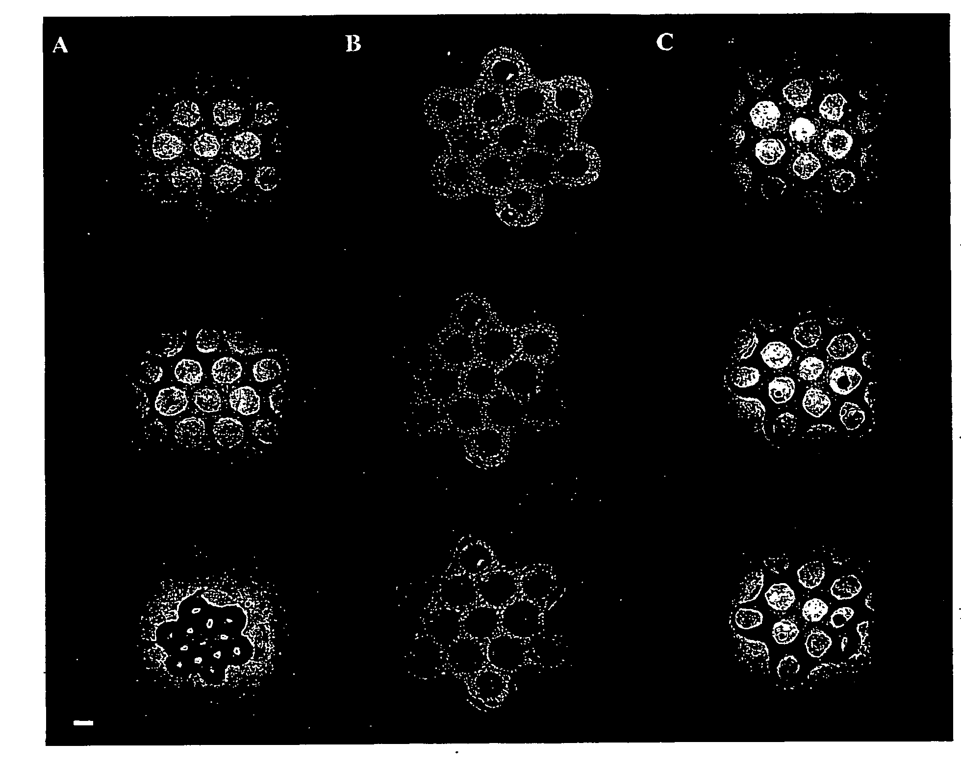
[0088]Human umbilical cord vascular endothelial cells (HUVEC) were seeded alone and simultaneously in co-culture with normal human diploid fibroblasts, the latter of which were also seeded alone. To visualize the different cell types, Cell Tracker™ fluorescent living cell stain was used. A freshly trypsinized suspension of HUVECs was incubated in 5 μM green fluorescent Cell Tracker™ (in cell culture medium) and a fibroblast suspension was incubated in 5 μM red fluorescent Cell Tracker™ for 45 minutes. Cell suspensions were centrifuged, Cell Tracker™ was aspirated off, and the cells were re-suspended in fresh media and incubated for 30 minutes.

[0089]Cell suspensions were then seeded into the seeding chambers of the aggregation devices made in accordance with Example 1 above. 0.50 million HUVECs alone (homogeneous population), 0.50 million fibroblasts alone (homogeneous population) and 0.25 million HUVEC and 0.25 million fibrob...


PUM

PropertyMeasurementUnit
widthaaaaaaaaaa
widthaaaaaaaaaa
widthaaaaaaaaaa

Abstract

The invention is a cell aggregation device comprising a hydrogel substrate having at least one, preferably a plurality, of cell-repellant compartments recessed into the uppermost surface. Each compartment is composed of an upper cell suspension seeding chamber having an open uppermost portion and a bottom portion, and one, or more than one, lower cell aggregation recess connected to the bottom portion of the upper cell suspension seeding chamber by a port. The diameter of the port may be fully contiguous with the walls of the chambers and walls of the recesses, or the diameter of the port may be more narrow than the walls of the chamber but fully contiguous with the walls of the recesses or more narrow than both the walls of the chamber and the walls of the recesses. The upper cell suspension seeding chambers are formed and positioned to funnel the cells into the lower cell aggregation recesses through gravitational force. The aggregation recesses are formed and positioned to promote cellular aggregation by coalescing cells into a finite region of minimum gravitational energy, increasing intercellular contact and minimizing or preventing cell adherence to the substrate. A device for encapsulating aggregates of live cells is provided. The device comprises (i) a biocompatible, bio-sustainable substrate having a cell-encapsulating face composed of one or more biocompatible, bio-sustainable, spaced-apart, cell-encapsulating compartments extending therefrom and (ii) a coating layer composed of a biocompatible, bio-sustainable polymer that completely surrounds the substrate and the cell-encapsulating compartments. A method for making the device is also provided.

Description

FIELD OF THE INVENTION[0001]The invention concerns cell culture aggregation and encapsulation devices and methods useful in cell culture and in tissue engineering and reconstruction techniques.BACKGROUND OF THE INVENTION[0002]The laboratory study of cells and groups of cells has been hampered by the inability to reproduce the cell's native environment on the benchtop. For example embryonic stem cells plated on microliter plates do not aggregate into homogeneous embryoid bodies in a controlled and reproducible manner; they grow across the entire bottom surface of the plate. Unlike cells cultured on a monolayer, aggregated cells tend to retain their in vivo morphology, and as a result, produce more signaling factors. By their nature, because aggregates are formed through cell-cell junctions, the possibility of anoikis is greatly reduced, allowing aggregates to remain viable over significantly longer periods of time. Aggregates allow cells to be packed into close proximity with each ot...

Claims


Application Information

Patent Timeline
Patent Type & Authority Applications(United States)
IPC IPC(8): C40B50/06C12M1/00C12N5/00B29C33/40C40B60/00
CPCC12N5/0012C12N5/0062C12M25/00C12N2533/74C12N2533/40C12M23/12C12M25/14C12M21/08B33Y80/00
Inventor MORGAN, JEFFREYCHAI, PETERNAPOLITANO, ANTHONYMATHIOWITZ, EDITHDEAN, DYLAN
Owner BROWN UNIVERSITY
Learn More