
Exhaust gas heat exchanger with integrated mounting interface

a heat exchanger and exhaust gas technology, applied in the field of exhaust gas recirculation systems, can solve the problems that the combustion gas cannot be recirculated to the intake side immediately after having left the combustion chamber of the internal combustion engine, and it is difficult if not impossible to design the surface of a metallic cast part as inert comparable with a stainless steel surface, etc., to achieve efficient space occupancy, increase the number of flow cross section constrictions, and improve the effect of manufacturing efficiency

Active Publication Date: 2009-01-15
HANON SYST
View PDF15 Cites 8 Cited by
  • Summary
  • Abstract
  • Description
  • Claims
  • Application Information

AI Technical Summary

Benefits of technology

[0016]If the housing cover comprises the proposed bracings in the region of the coolant inlet and / or the coolant outlet, it is possible to completely eliminate undercuts on the housing case, which can be configured to be a cast part for example. This is due to the fact that it is not necessary for the housing case lying behind to support the housing cover in the region of the coolant inlet and / or the coolant outlet since, by virtue of the bracings proposed herein, the housing cover exhibits sufficient inherent stiffness in the regions in which forces prevail, which originate from the pressure of the coolant and deform the housing cover.
[0017]In another preferred implementation, the exchanger tube is designed so that a flow path forms in the exchanger tube, at least in its portion disposed inside the housing of the heat exchanger, the flow path running therein as a winding flow path including an angle of rotation a of at least 135°, preferably however an angle of rotation a of 180°. In the last configuration mentioned, heat exchangers with particularly high space savings can be realized.
[0019]In the previously mentioned configuration in which the flow path includes an angle of rotation a of 180°, the exchanger tube is preferably curved into a substantially U or semi-circular shape. This configuration of the exchanger tube is particularly efficient to manufacture and concurrently allows for efficient space occupancy of the inner volume of the heat exchanger housing.
[0020]In a preferred developed implementation, rather than one single exchanger tube there is provided a plurality of exchanger tubes that are disposed in the housing of the heat exchanger and form a bundle connected in parallel in terms of fluid flow. The flow paths forming in the exchanger tubes have preferably no contact to each other between their respective in- and outlets so that an increased number of flow cross section constrictions are avoided when passing through the exhaust path in the heat exchanger of the invention. This offers substantial advantages with respect to the pressure drop occurring in the exhaust gas heat exchanger and in particular also with respect to the deposits of residues originating from the combustion exhaust.
[0023]Particular advantages are obtained if the housing portion on which the inlet and the outlet of the exchanger tube as well as the coolant inlet and the coolant outlet are disposed are made from the same material as the exchanger tube. If particularly high demands are placed on the heat load capacity of the exhaust gas heat exchanger of the invention, both the previously mentioned housing portion and the exchanger tube / the exchanger tubes are preferably made from stainless steel. If the thermal demands are slightly less, an implementation made from aluminium or from an aluminium alloy can be sufficient.

Problems solved by technology

Since the efficiency of an internal combustion engine is typically dependent on the temperature of the combustion air fed into the combustion chamber of the internal combustion engine, the combustion gases cannot be recirculated to the intake side immediately after having left the combustion chamber of the internal combustion engine.
Since the very hot combustion gases are reactive due to the fact that the fuel never burns completely, the problem here is that it is technically difficult if not impossible to design the surfaces of a metallic cast part as inert surfaces comparable with a stainless steel surface.

Method used


Image

  • Exhaust gas heat exchanger with integrated mounting interface
  • Exhaust gas heat exchanger with integrated mounting interface
  • Exhaust gas heat exchanger with integrated mounting interface

Examples


Embodiment Construction

[0038]The following detailed description and appended drawings describe and illustrate various embodiments of the invention. The description and drawings serve to enable one skilled in the art to make and use the invention, and are not intended to limit the scope of the invention in any manner. In respect of the methods disclosed, the steps presented are exemplary in nature, and thus, the order of the steps is not necessary or critical.

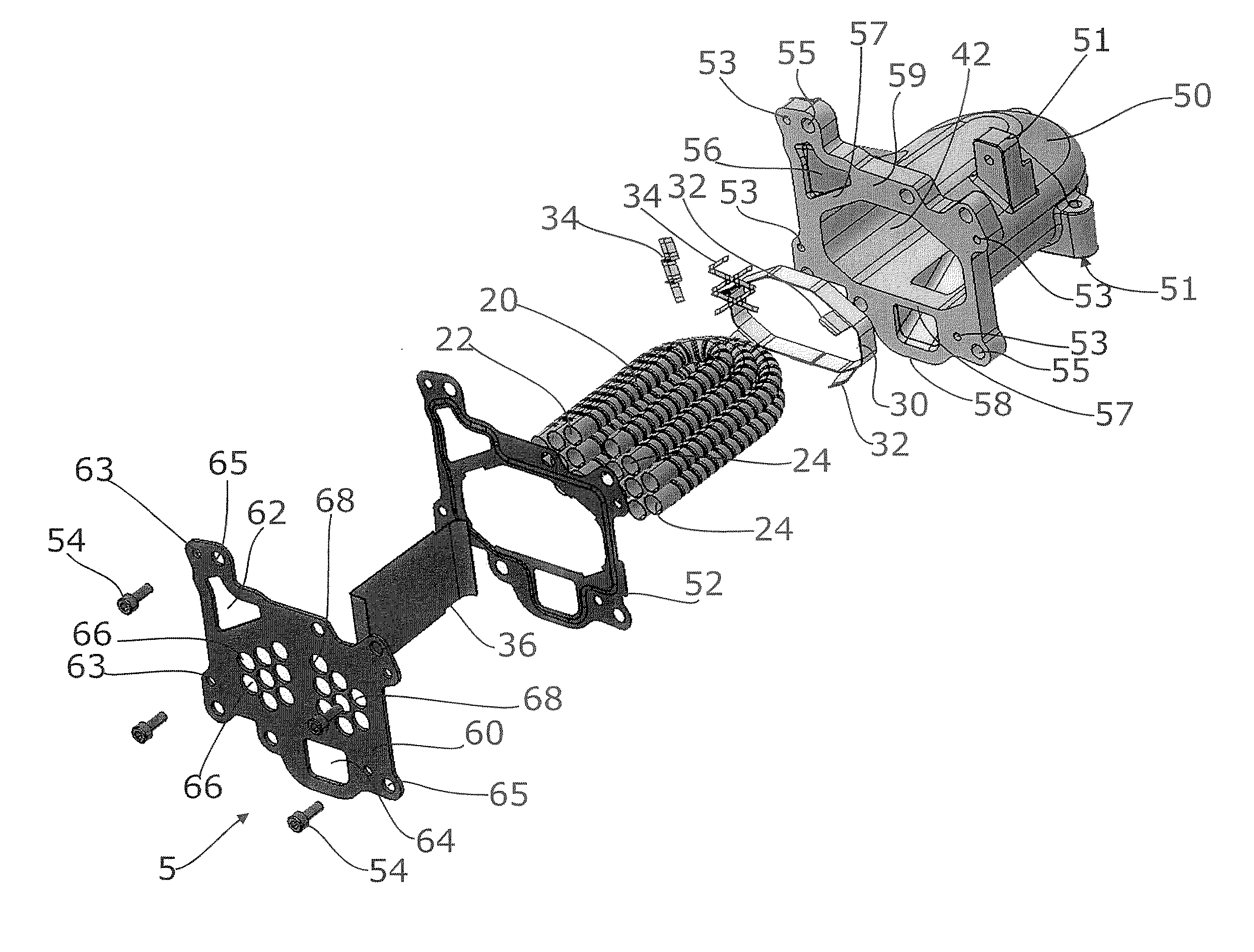
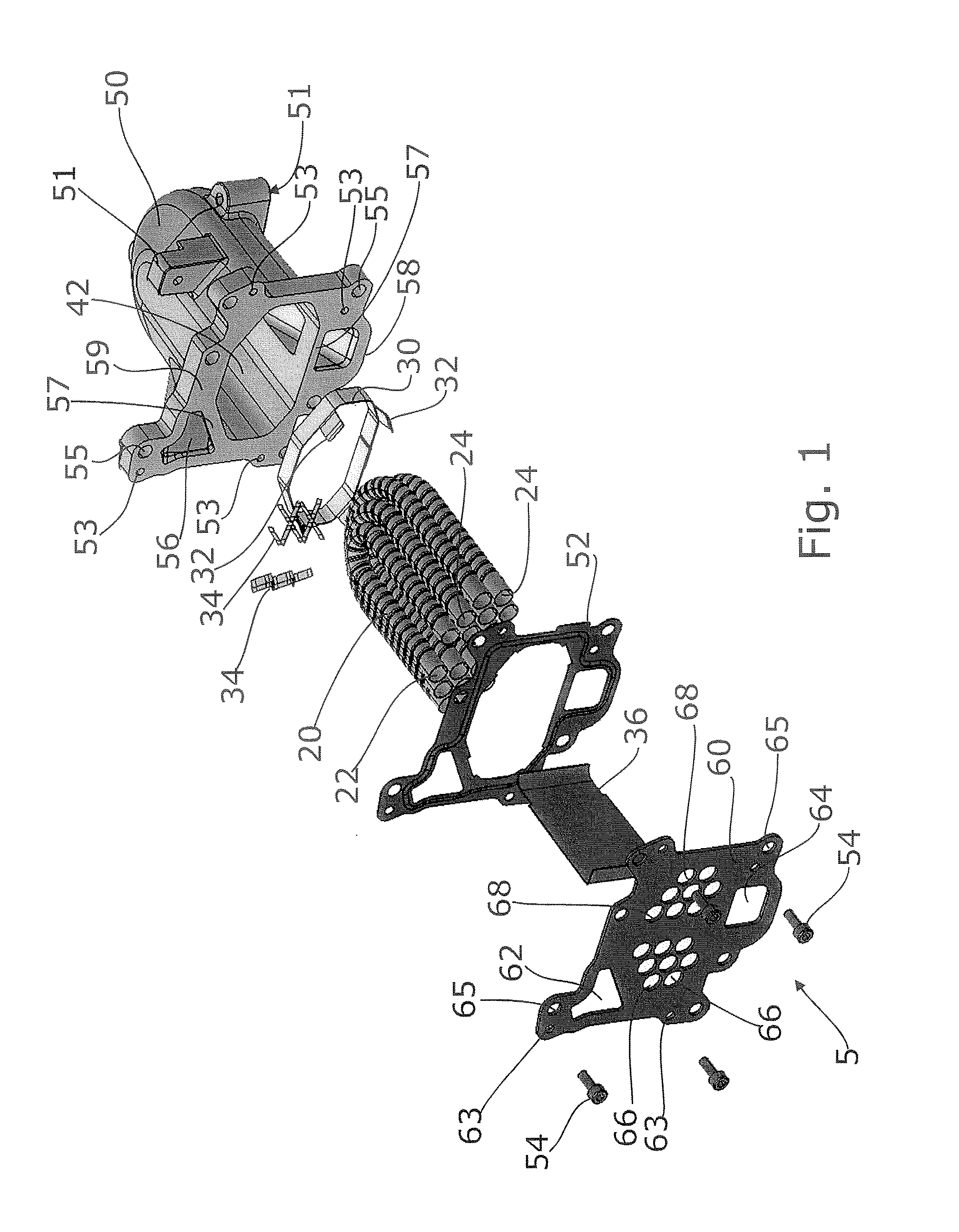
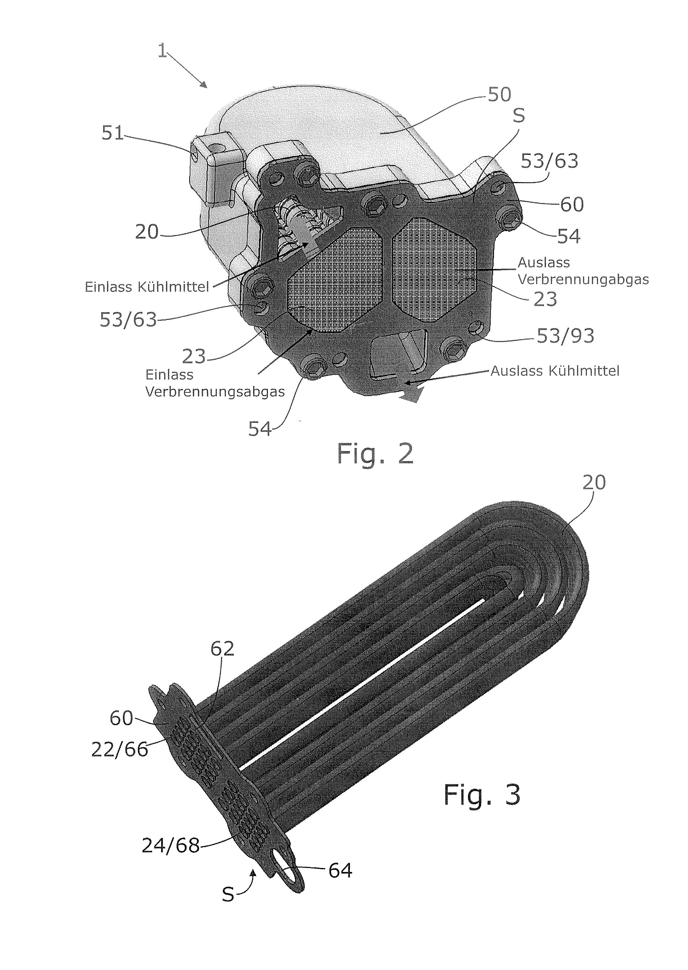
[0039]FIG. 1 shows an exploded view of an exhaust gas heat exchanger 1 of the invention according to a first exemplary embodiment. The heat exchanger 1 includes a housing 40 consisting of a housing case 50 closed by means of a housing cover 60. The housing case 50 is configured to be a cast part and may be made from aluminium die casting in particular. Alternatively, the housing case 50 in the exemplary embodiment shown may be made from any material that can be processed by casting on the one side and that has sufficient thermal stability on the other...


PUM


Abstract

A heat exchanger for an exhaust gas train of a motor vehicle with an exhaust gas carrying exchanger tube that is formed separately and is disposed in a closed housing formed separately, a coolant flowing through the housing and around the outer surface of the exchanger tube. The housing includes a housing portion that forms one common mechanical interface for connecting the heat exchanger to the exhaust gas train and a coolant circuit of the motor vehicle.

Description

CROSS-REFERENCE TO RELATED APPLICATION[0001]This application claims the benefit of German provisional patent application serial no. DE 102007032187.4 filed Jul. 11, 2007, and German non-provisional patent application serial no. DE 102008001659.4 filed May 8, 2008, each of which is hereby incorporated herein by reference in its entirety.FIELD OF THE INVENTION[0002]The invention relates to a heat exchanger for an exhaust train of a motor vehicle, and more specifically for an exhaust gas recirculation system for an internal combustion engine of a motor vehicle.BACKGROUND OF THE INVENTION[0003]Due to the ever more stringent legal regulations regarding exhaust emission of motor vehicles, in particular, regarding emission of nitrogen oxides, recirculation of combustion exhaust on the inlet side of the internal combustion engine is state of the art in the field of internal combustion engines. The combustion gases themselves do not participate again in the combustion process in the combusti...

Claims


Application Information

Patent Timeline
IPC IPC(8): F01N5/02
CPCF02M25/0737F28D7/06F28F1/06F28F1/08F28F9/0219F28F9/182Y02T10/121F01N3/0205F28F9/007F28F9/00F02M26/32
Inventor CAPELLE, ANDREASFISCHER, OLIVERDIEHL, PETERGAUSS, MICHAELREPA, ANDREJHEBERT, GUILLAUME
Owner HANON SYST
Learn More