Exhaust heat recovery device

a heat recovery device and exhaust heat technology, applied in indirect heat exchangers, machines/engines, lighting and heating apparatus, etc., can solve the problems of high manufacturing cost, thermal stress, and holes in the bellows, and achieve the effect of preventing the occurrence of holes and simple structur

Inactive Publication Date: 2009-01-01
DENSO CORP
View PDF20 Cites 8 Cited by
  • Summary
  • Abstract
  • Description
  • Claims
  • Application Information

AI Technical Summary

Benefits of technology

[0008]The invention has been made in view of the foregoing problems, and it is an object of the invention to provide an exhaust heat recovery device that can release thermal stress with a simple structure, while preventing occurrence of holes due to external corrosion.
[0010]In this way, at least one of the evaporation side connection portion and the condensation side connection portion has a part (or the whole) thereof curved. When a difference in temperature between the evaporator and the condenser is generated, an elastic deformation of the curved portion can absorb thermal stress caused by a difference in thermal expansion. At this time, bellows do not need to be provided in the evaporation side and condensation side connection portions, thereby releasing the thermal stress with a simple structure while preventing the occurrence of holes due to external corrosion.
[0011]In the exhaust heat recovery device, the working fluid evaporated by the evaporator flows into the condenser through the evaporation side connection portion. The condensed liquid fluid flows into the evaporator through the condensation side connection portion. Thus, there occurs a difference in water level (water head) of the working fluid (liquid) between the evaporator and the condenser, depending on a balance between evaporation of the working fluid at the evaporator and condensation of the working fluid at the condenser. The difference in water head allows the working fluid to be refluxed from the condenser to the evaporator, thereby causing the circulation of the working fluid.

Problems solved by technology

The difference in temperature between the evaporator J1 and the condenser J2 may disadvantageously cause thermal stress due to a difference in thermal expansion between the evaporation side connection portion J71 and the condensation side connection portion J72.
The structure, however, may be complicated, resulting in high manufacturing cost.
This may cause holes in the bellows due to corrosion from an external side, that is, from the side in contact with atmosphere.

Method used


Image

  • Exhaust heat recovery device
  • Exhaust heat recovery device
  • Exhaust heat recovery device

Examples


first embodiment

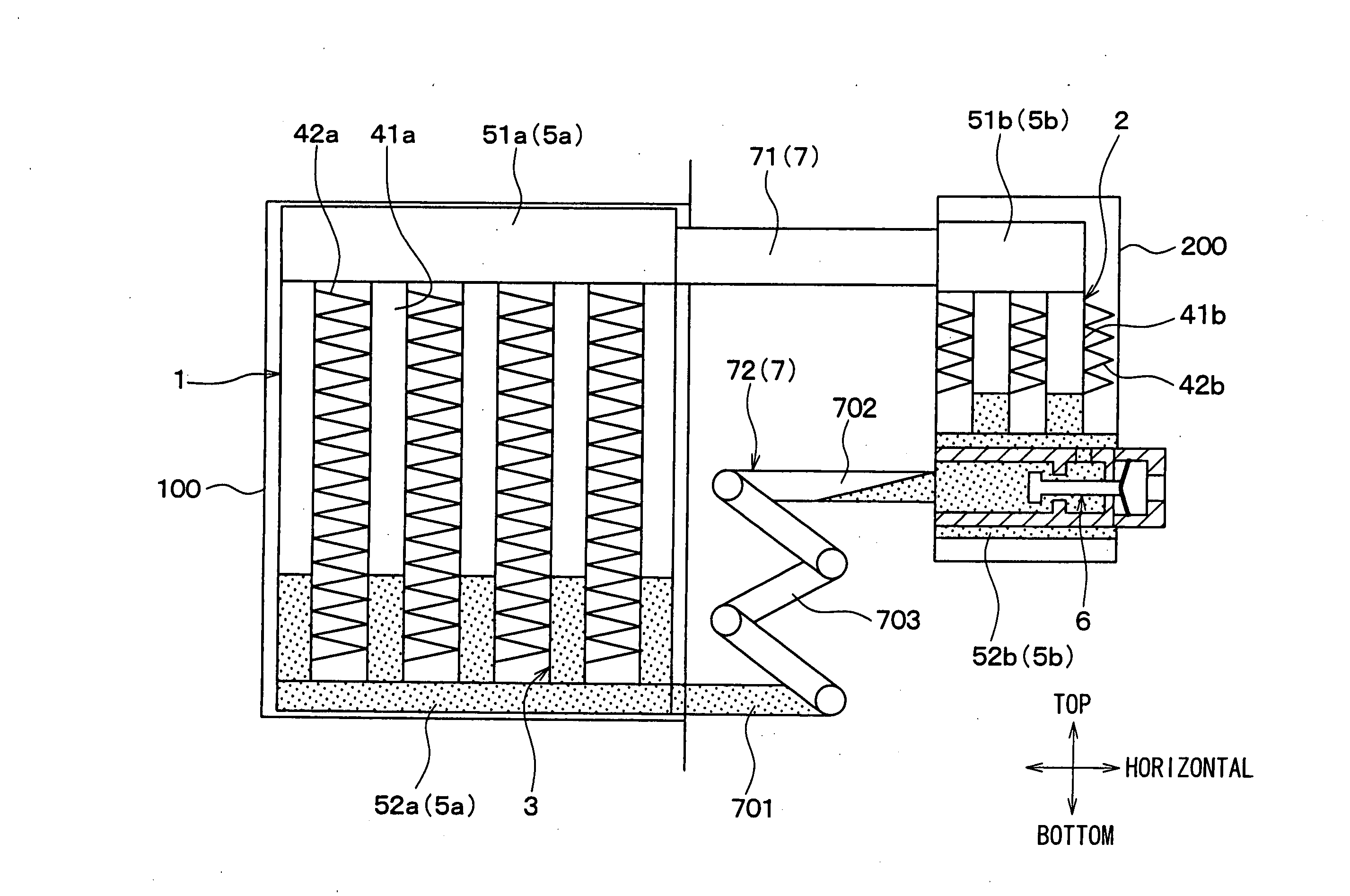
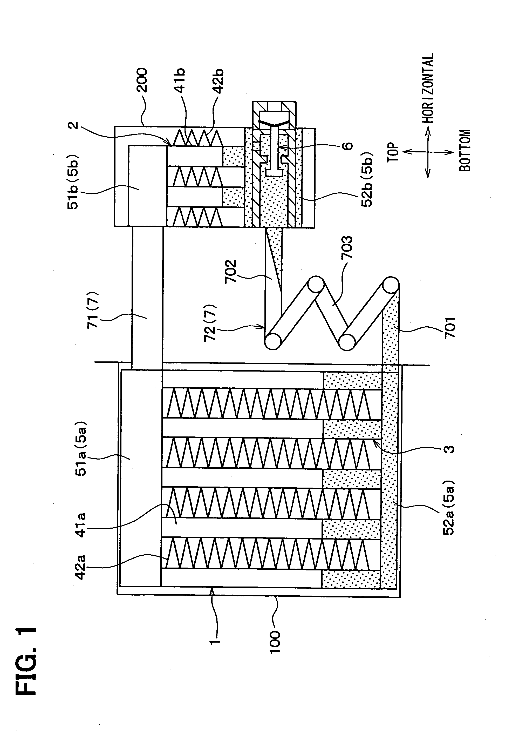
[0022]A first embodiment of the invention will be described with reference to FIG. 1. An exhaust heat recovery device of this embodiment is adapted to recover exhaust heat of an exhaust gas from an exhaust system of an engine (e.g., internal combustion engine) of a vehicle, and to use the exhaust heat for promotion of warning or the like.

[0023]FIG. 1 is a schematic sectional view showing an example of the exhaust heat recovery device of the first embodiment. As shown in FIG. 1, the exhaust heat recovery device of this embodiment includes an evaporator 1 and a condenser 2. The evaporator 1 and the condenser 2 are connected to each other to form a loop-type heat pipe 3.

[0024]The heat pipe 3 is provided with an sealing portion (not shown), from which the heat pipe 3 is evacuated to vacuum (decompressed). After being filled with a working medium, the sealing portion is sealed. The working fluid in use is water, for example. The working fluid for use may include alcohol, fluorocarbon, fl...

second embodiment

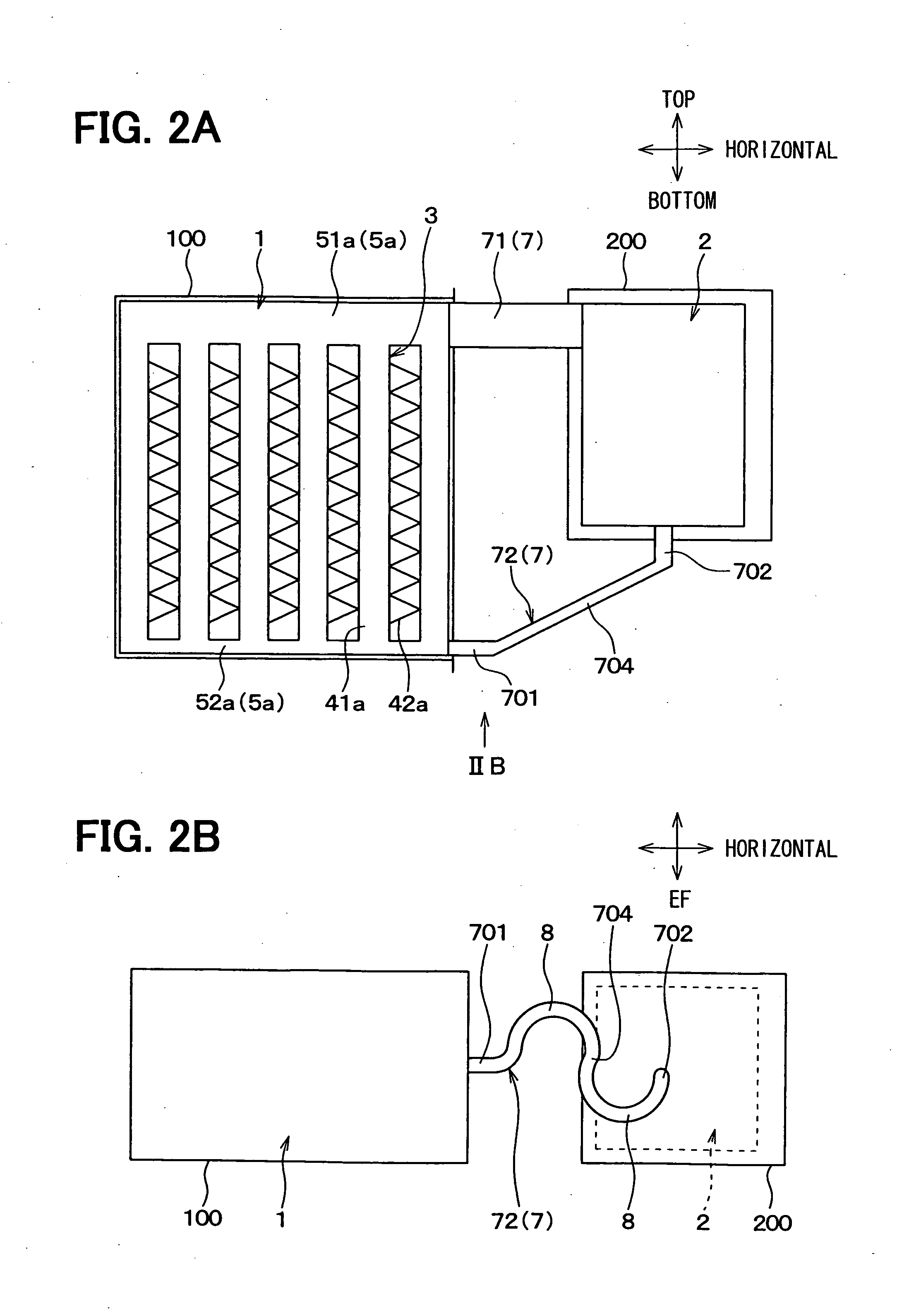
[0040]Now, a second embodiment of the invention will be described below based on FIGS. 2A and 2B. The elements having the same functions as those of the first embodiment will be designated by the same reference numerals, and a description thereof will be described below.

[0041]FIG. 2A is a sectional view showing an exhaust heat recovery device according to the second embodiment, and FIG. 2B is a diagram viewed along an arrow IIB in FIG. 2A. In FIGS. 2A and 2B, representation of the detailed structure of the condenser 2 will be omitted.

[0042]As shown in FIGS. 2A and 2B, in the second embodiment, a condensation side connection portion 72 includes a lower member 701 having one end connected to the second evaporation side header 52a and extending substantially in the horizontal direction toward the condenser 2, and an upper member 702 having one end connected to the lower end of the second condensation side header (not shown) of the condenser 2 and extending substantially in the vertical...


PUM


Abstract

An exhaust heat recovery device includes an evaporator disposed to evaporate a working fluid by exchanging heat between a heating fluid and the working fluid, a condenser disposed to cool and condense the working fluid by exchanging heat between a fluid to be heated and the working fluid evaporated by the evaporator, an evaporation side connection portion for guiding the working fluid evaporated by the evaporator to the condenser, and a condensation side connection portion for guiding the working fluid condensed by the condenser to the evaporator. Furthermore, at least one of the evaporation side connection portion and the condensation side connection portion has a curved portion.

Description

CROSS REFERENCE TO RELATED APPLICATION[0001]This application is based on Japanese Patent Applications No. 2007-170078 filed on Jun. 28, 2007, and No. 2008-034082 filed on Feb. 15, 2008, the contents of which are incorporated herein by reference in its entirety.FIELD OF THE INVENTION[0002]The present invention relates to an exhaust heat recovery device used for a vehicle.BACKGROUND OF THE INVENTION[0003]In recent years, techniques have been known which are adapted to recover heat of an exhaust gas from an exhaust gas system of an engine of a vehicle using the principle of a heat pipe, so as to use the recovered exhaust heat for promotion of warming or the like. Such an exhaust heat recovery device includes an evaporator of the heat pipe disposed in an exhaust pipe of the engine and a condenser of the heat pipe disposed in a coolant passage of the engine. Furthermore, the exhaust heat recovery device is configured to heat coolant of the engine by the exhaust heat of the exhaust gas (s...

Claims


Application Information

Patent Timeline
Patent Type & Authority Applications(United States)
IPC IPC(8): F01N3/02
CPCB60H1/00571F01N5/02Y02T10/16F28D15/06F28D21/0003F28D15/0266Y02T10/12
Inventor MIYAGAWA, MASASHIMURAMATSU, KENSHIROUYAMANAKA, YASUTOSHIKAFUKU, KAZUAKI
Owner DENSO CORP
Why Eureka
Try Eureka