
Complex Pattern Generator for Analysis of High Speed Serial Streams

a serial stream and complex pattern technology, applied in the direction of testing circuits, instruments, transmission monitoring, etc., can solve the problems of long startup time, system level test will eventually fail, and specific data sequences within large test patterns, so as to facilitate signal testing and verification, accurately reflect actual traffic, and accurately test the boundaries of the device

Inactive Publication Date: 2008-12-11
AVAGO TECH WIRELESS IP SINGAPORE PTE
View PDF8 Cites 4 Cited by
  • Summary
  • Abstract
  • Description
  • Claims
  • Application Information

AI Technical Summary

Benefits of technology

[0011]The present invention provides systems, devices and methods for generating user-defined test patterns within serial controllers to facilitate signal testing and verification. These user-defined test patterns may be generated to more accurately reflect the actual traffic of a device-under-test or system, as well as allow a test engineer to more accurately test the boundaries of the device or system.
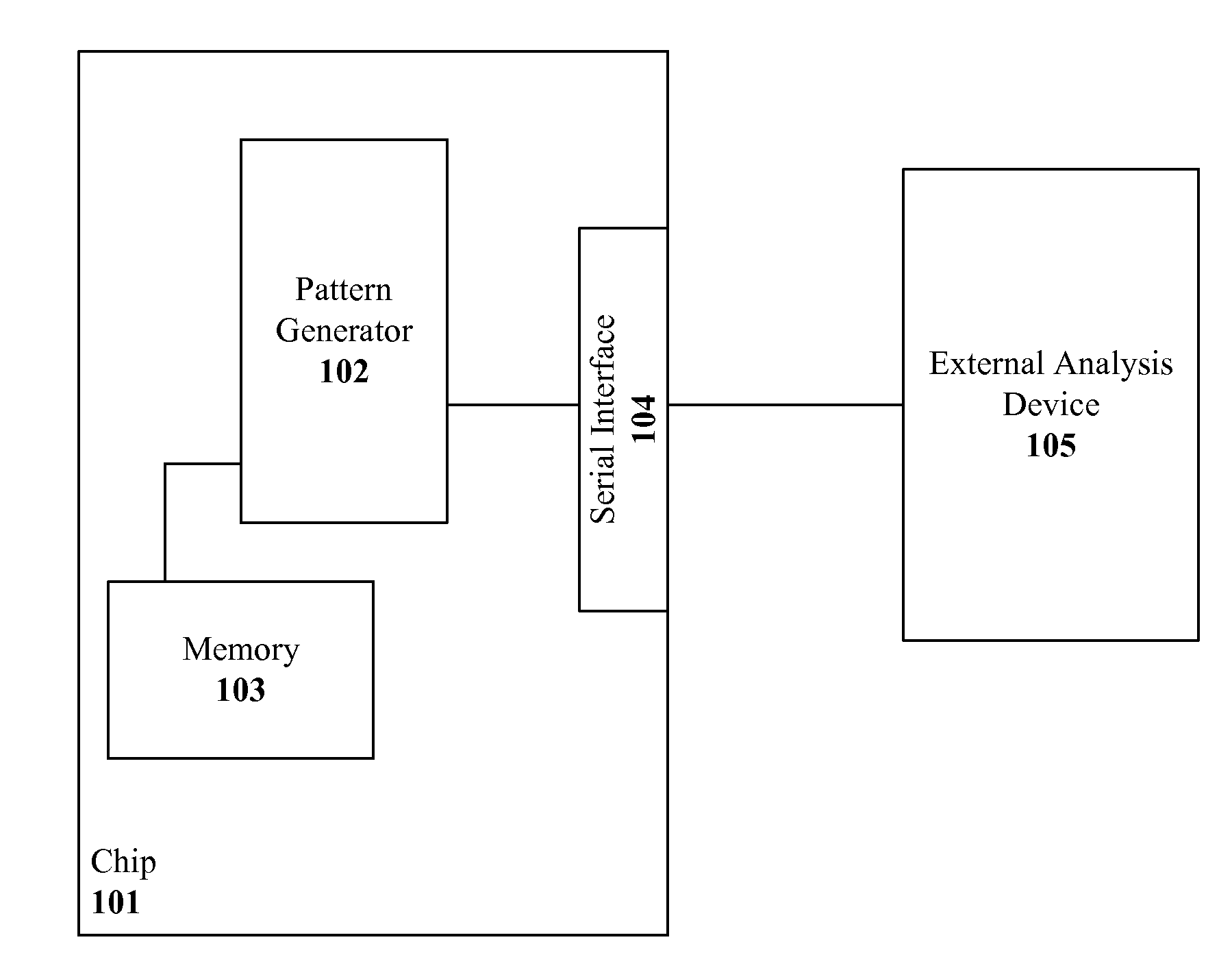
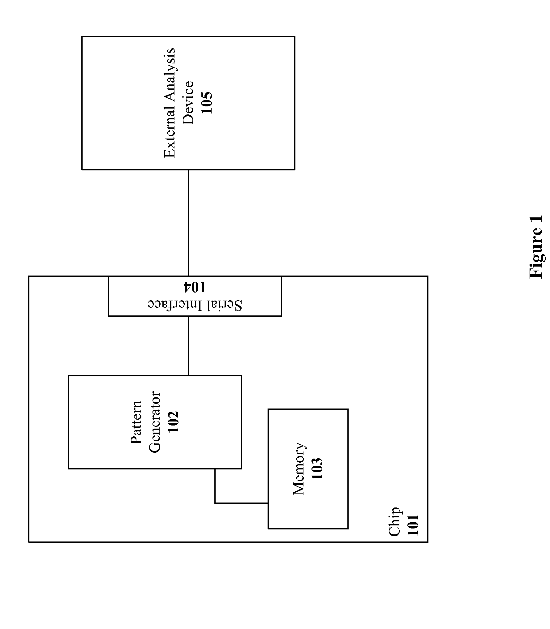
[0012]In various embodiments of the invention, a programmable pattern generator is provided for generating user-defined test patterns that may be used during a testing procedure. This programmable pattern generator allows a user to define a particular test pattern by providing bit-by-bit test values, by defining a combination of canned sequences, or by supplementing one or more canned sequences with additional test bits. If canned patterns are used in the generation of user-defined test patterns, these canned patterns may be retrieved in a memory and the user-defined pattern may be generated by accessing an internal register of the chip. As a result, a user may define a particular test pattern for a certain device or system to improve the corresponding test procedure.

Problems solved by technology

If an envelope of performance is to be tested, a system level test will eventually fail and require a long startup time to get back to a working point.
However, the sequence of data within the large test pattern is specifically limited by the canned patterns stored within the memory 103.

Method used


Image

  • Complex Pattern Generator for Analysis of High Speed Serial Streams
  • Complex Pattern Generator for Analysis of High Speed Serial Streams
  • Complex Pattern Generator for Analysis of High Speed Serial Streams

Examples


Embodiment Construction

[0022]Systems, devices and methods for generating user-defined test patterns are described. In one embodiment of the invention, a programmable pattern generator is provided that generates test patterns as defined by a user. The test pattern may be generated at a bit-by-bit granularity or use one or more canned patterns stored within a memory.

[0023]In the following description, for purpose of explanation, specific details are set forth in order to provide an understanding of the invention. It will be apparent, however, to one skilled in the art that the invention may be practiced without these details. One skilled in the art will recognize that embodiments of the present invention, some of which are described below, may be incorporated into a number of different systems and devices. The embodiments of the present invention may also be present in software, hardware or firmware.

[0024]Structures and devices shown below in block diagram are illustrative of exemplary embodiments of the in...


PUM


Abstract

The present invention provides systems, devices and methods for generating user-defined test patterns within serial controller to facilitate signal testing and verification. These user-defined test patterns may be generated to more accurately reflect the actual traffic of a device-under-test or system, as well as allow a test engineer to more accurately test the boundaries of the device or system. In various embodiments of the invention, a programmable patterns generator is provided for generating user-defined test patterns that may be used during a testing procedure. This programmable pattern generator allows a user to define a particular test pattern by providing bit-by-bit test values, by defining a combination of canned sequences, or by supplementing one or more canned sequences with additional test bits.

Description

BACKGROUND[0001]A. Technical Field[0002]The present invention relates to test pattern generation and, more particularly, to the generation of user-defined test patterns for signal characterization and testing.[0003]B. Background of the Invention[0004]The application and importance of test pattern generators is well known. Pattern generators provide a test signal used for signal characterization and analysis within various electrical components and systems. These test patterns are used for testing devices such as integrated chips, systems, and communication paths to ensure proper operation of these devices and systems.[0005]The current solution for pattern generation allows a user to select one or more pre-stored “canned data patterns” within the memory of a testing device or device-under-test. Typically, the canned patterns are generated by looping a small pattern over multiple times in sequence to generate a longer test pattern. For example, the SAS / Fibre Channel specification defi...

Claims


Application Information

Patent Timeline
IPC IPC(8): G01R31/3183G06F11/00G01M99/00
CPCG01R31/31813G01R31/318307
Inventor ROMERO, GABRIEL L.GAUVIN, CORALYN S.
Owner AVAGO TECH WIRELESS IP SINGAPORE PTE
Learn More