
Structures for Low Cost, Reliable Solar Roofing

a solar roof and low-cost technology, applied in the field of photovoltaic devices, can solve the problems of significant relative cost of electrical connectors in the overall solar installation, and limit the additional installation cost of electricians, so as to reduce materials costs and simplify the configuration

Inactive Publication Date: 2008-12-11
AERIS CAPITAL SUSTAINABLE IP
View PDF24 Cites 239 Cited by
  • Summary
  • Abstract
  • Description
  • Claims
  • Application Information

AI Technical Summary

Benefits of technology

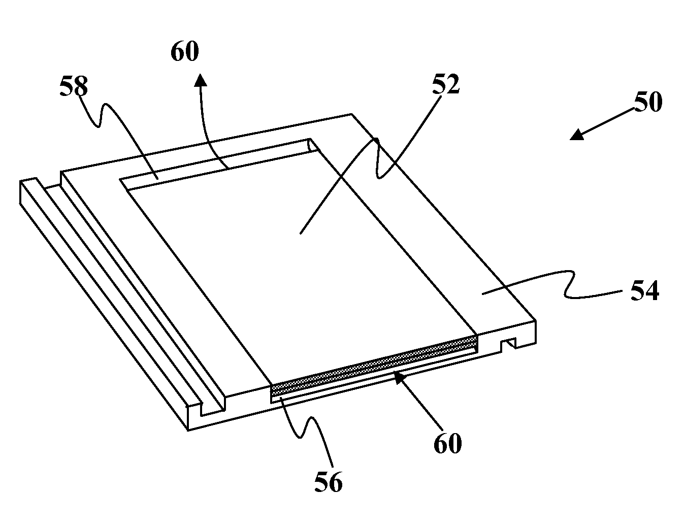
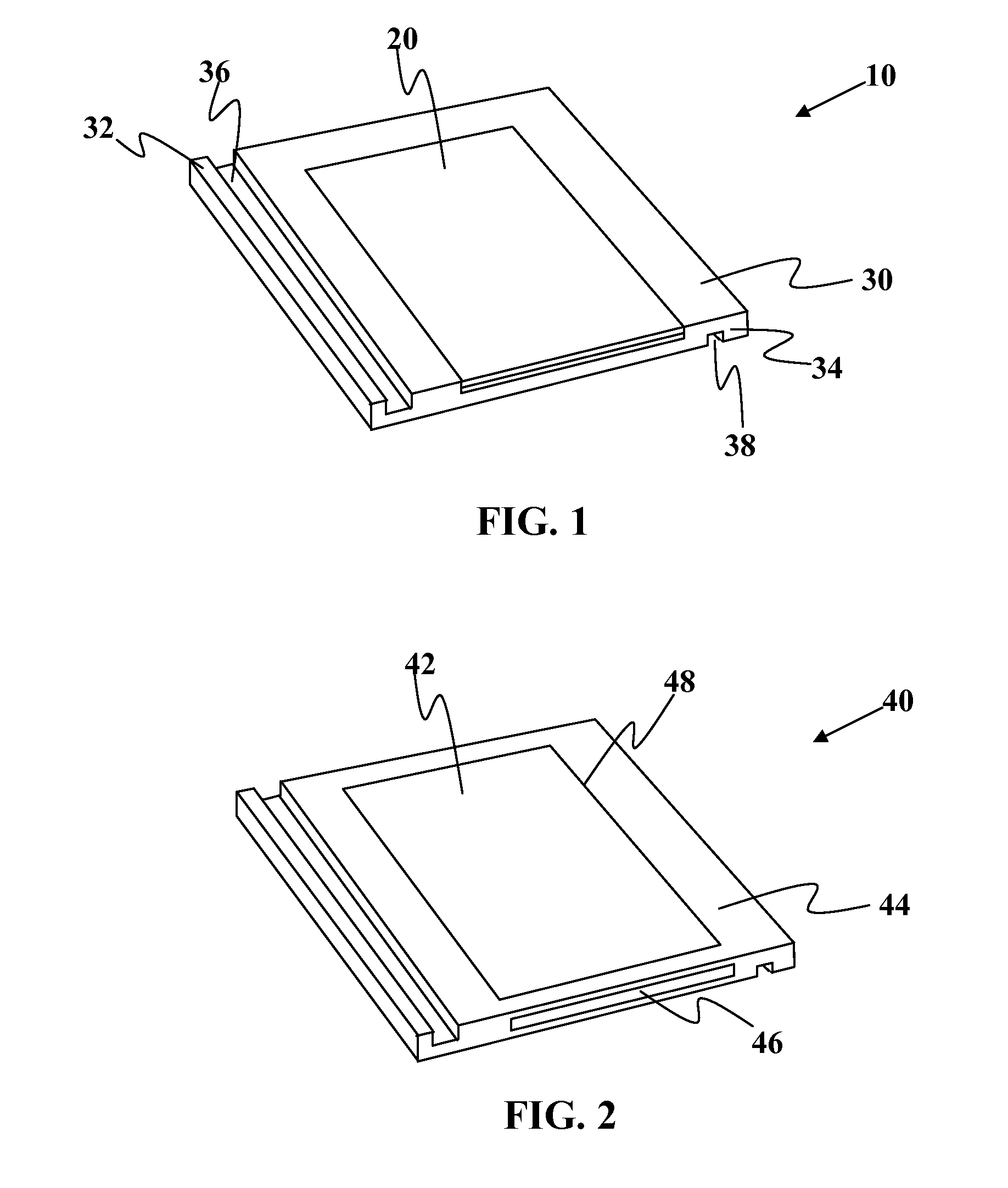
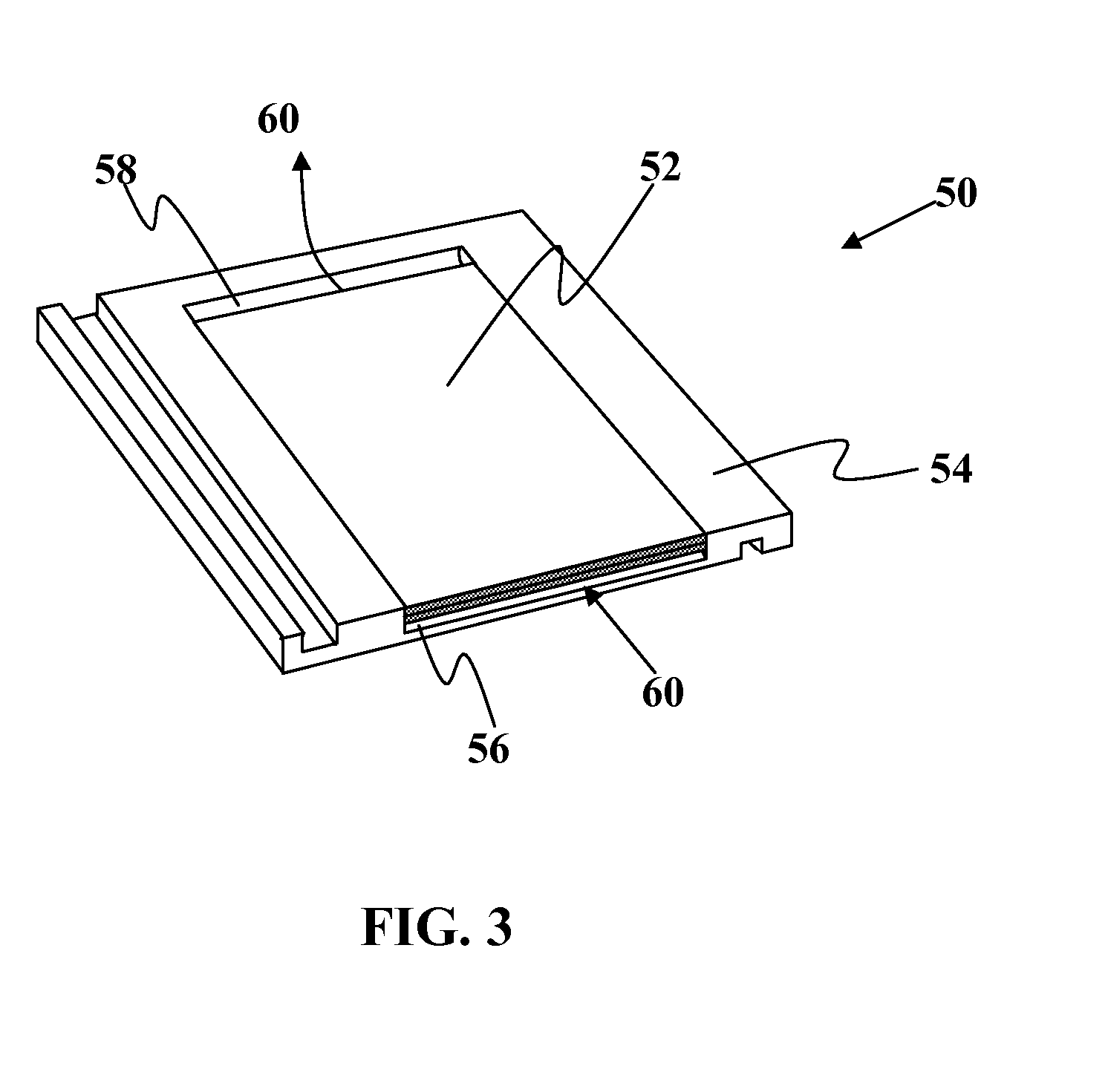
[0014]Embodiments of the present invention address at least some of the drawbacks set forth above. The present invention provides for the improved BIPV roofing tile design that simplifies the configuration and reduces the materials costs associated with such photovoltaic roofing elements. Although not limited to following, these improved roofing element designs are well suited for installation at dedicated sites where redundant elements can be eliminated where some common elements or features may be shared by many modules. It should be understood that at least some embodiments of the present invention may be applicable to any type of solar cell, whether they are rigid or flexible in nature or the type of material used in the absorber layer. Embodiments of the present invention may be adaptable for roll-to-roll and / or batch manufacturing processes. At least some of these and other objectives described herein will be met by various embodiments of the present invention.
[0015]In one embodiment of the present invention, a key feature of the new design, requiring significant development, is a cost-effective, intuitive, simple, secure, and optionally UL-approved electrical connection between tiles. If the tiles are small, the relative cost of electrical connectors in the overall solar installation is significant, requiring a low cost connector. This connector should automatically create an electrical contact when two neighboring solar tiles are installed next to each other. The contact will give affirmative feedback (visual, auditory, tactile, or the like) when the connection is made properly, enabling tile-to-tile installation by non-electricians. Additional technical specifications are mechanical robustness, corrosion resistance, reliable electrical connection, and the need to be safe to the touch during installation. Cabling is reduced to the ends of each tile row, and together with the elimination of a junction box, this can be the lowest cost BIPV tile on the market.
[0016]Large scale solar panels distribute the cost of one set of electrical connectors and mounting over a larger quantity of cells. This has led to solar module sizes that, optimized for commercial rooftops and green field installations, are significantly larger than a standard roof tile format, which over decades has been fine-tuned for optimum balance between installation effort and flexibility. As multi-faceted residential roofs have gables, chimneys and partial shading, which all restrict the area where solar modules can be mounted, a smaller form factor is desirable to maximize the flexibility. The foil substrate can be cut into a wide range of cell formats, increasing the format options to fit into a single tile.

Problems solved by technology

If the tiles are small, the relative cost of electrical connectors in the overall solar installation is significant, requiring a low cost connector.
Large scale solar panels distribute the cost of one set of electrical connectors and mounting over a larger quantity of cells.
Additional installation cost is limited to an electrician connecting the start and end tiles of a row to the inverter or to each other.

Method used


Image

  • Structures for Low Cost, Reliable Solar Roofing
  • Structures for Low Cost, Reliable Solar Roofing
  • Structures for Low Cost, Reliable Solar Roofing

Examples


Embodiment Construction

[0048]It is to be understood that both the foregoing general description and the following detailed description are exemplary and explanatory only and are not restrictive of the invention, as claimed. It may be noted that, as used in the specification and the appended claims, the singular forms “a”, “an” and “the” include plural referents unless the context clearly dictates otherwise. Thus, for example, reference to “a material” may include mixtures of materials, reference to “a compound” may include multiple compounds, and the like. References cited herein are hereby incorporated by reference in their entirety, except to the extent that they conflict with teachings explicitly set forth in this specification.

[0049]In this specification and in the claims which follow, reference will be made to a number of terms which shall be defined to have the following meanings:

[0050]“Optional” or “optionally” means that the subsequently described circumstance may or may not occur, so that the des...


PUM


Abstract

Improved photovoltaic devices, and more specifically, improved building integrated photovoltaic devices are described herein. In one embodiment, the photovoltaic roofing structure may be comprised of a roofing tile having a top surface, a bottom surface, and a recessed portion; a photovoltaic module sized to fit within the recessed portion of the roofing structure.

Description

CROSS-REFERENCE TO RELATED APPLICATION[0001]This application claims priority to U.S. Provisional Application Ser. No. 60 / 916,551 filed May 7, 2007 and fully incorporated herein by reference for all purposes.FIELD OF THE INVENTION[0002]This invention relates generally to photovoltaic devices, and more specifically, to improved building integrated photovoltaic devices.BACKGROUND OF THE INVENTION[0003]Building integrated photovoltaic (BIPV) roof tiles currently represent a small portion of the overall photovoltaic market, in spite of the seemingly compelling proposition of integrating an energy source into a roofing component. Market adoption has been slow due in part to the relatively high cost of roofing tiles integrated with PV modules. High cost is currently incurred since solar modules are not designed to serve as a bulk construction material, but rather integrated into a home as a custom electrical installation. There are several barriers within the current residential rooftop BI...

Claims


Application Information

Patent Timeline
Patent Type & Authority Applications(United States)
IPC IPC(8): E04D13/18H01L31/048H01L31/052
CPCH01L31/02008H01L31/052H02S20/25Y02B10/20Y02E10/50Y02B10/12F24S20/69H01L31/0521Y02A30/60Y02B10/10Y02E10/40Y02E10/44
Inventor STANCEL, ROBERTROSCHEISEN, MARTIN R.SAGER, BRIAN M.ADRIANI, PAUL M.
Owner AERIS CAPITAL SUSTAINABLE IP
Learn More